
50MHz Transmitter alarmer with PIC16F84
IR-part: The IR-diode used is CLS172. It is powered with 5V and the output signal is first filtered, and the signal is added to a 2.5V bias. A simple operational amplifier (OP) is used to amplify the signal. The gain is set by the ratio of two resistors, 1M/200 Ohm = 5000 times. The DTMF circuit uses the 3.57954MHz frequency to make the dual tones. This DTMF circuit is in a DIL 20 capsule and is controlled by a parallel interface. The output from the DTMF circuit (pin 8) has 2.6Vpp and a DC bias of 2.5V. This level is quite large and could modulate the transmitter as it is, but it has been chosen to amplify the signal even more before it modulates the FM transmitter. A simple NPN (BC817-25) transistor is used to gain the signal. The resistors R1 and R4 set the gain and the DC bias. If another transistor is used, the values of these two resistors may need to be changed. An oscilloscope can be connected to the collector to monitor the output. Two potentiometers (500 ohm and 200k) can be used instead of R1 and R4. R1 will set the DC bias, and R4 will set the gain. It is important to ensure a clean shape of the amplified signal.
In the schematic, pin 8 at MT8880 divides the output signal with two resistors, 10k and 1k. The output signal at pin 8 is 2.6Vpp, and after the divider, it will be 230mVpp. The signal passes through C4 to remove any DC bias, and the transistor with R1 and R2 amplifies the signal to 4.8Vpp with a DC bias of 4.4V. The initial division of the signal with two resistors followed by amplification is done to maximize the DTMF signal. The chosen values of R1 and R2 provide a gain of 21 times (26dB) and a DC bias of 4.4V. The output signal from the MT8880 at pin 8 is 2.6Vpp, then divided to 230mVpp, and subsequently amplified to 4.8Vpp at the collector, with the signal swinging around the 4.4V bias.
The voltage level at the cathode of the varicap diode BB132 modulates the frequency. The voltage here can theoretically range from 0 to 9V, leading to frequency changes of a few kilohertz. A higher modulation voltage is desired for improved signal-to-noise performance. At pin 6 of the OP, the output is 2.5 VDC bias and an AC signal of 0.5-2Vpp depending on the incoming IR to the diode. An oscilloscope can be connected here to monitor the output signal. By placing the Fresnel lens over the IR-diode and moving a hot object in front of the detector, the signal amplitude can be observed changing. Testing the IR unit before proceeding with the project is recommended.
This configuration is designed to create a highly sensitive and intelligent unit. A voltage comparator could have been used to check for changes in the IR-detector level; however, it was noted that the DC level changes slightly and at very low frequencies, along with noise from the IR-diode that adds to the signal. The A/D converter samples the signal from the IR-diode eight times per second for effective monitoring.This project is about an IR-detector (Infra Red) combined with a 100mW 50MHz transmitter. The detector is sensitive to changes in IR-spectrum and is commonly used in burglar alarms. When the detector sens a person/animal/ghost/angry clown, it will transmitt a warning signal to a portable receiver and you will get a pre-warning. This project is aimed for typical 007-persons who doesn't want to be surprised by other. Maybe you have been in some situation where you wanted to know if there was any person comming or leaving.
I will not ask you why! Maybe you sleep on the second floor and you want to have a pre-warning if any one should be at first floor or if you are out camping and you don't want any "blairwitch" to sneak up on you! This project is very useful in many situation, I just want you to use this in good purpose. The total project consist of a 50MHz portable transmitter with an IR-detector sensitive for motion, and a 50MHz portable receiver.
In this page I will explain the transmitter part. The first part is a IR-detector. Inside the detector is two or more IR-seisitive surfaces. The IR-diod is most sensitive to IR-changes. To gain sensitivity, filtering and IR-viewing angle, one use a lens in front of the IR-diod. This lens is called fresne lens. It is the window you see on the alarms. The output signal from the IR-diod has to be amplified to obtain a useful signal. The next block is a preamplifier. This amplifier amplify the signal about 70dB or 5000 times. Since the IR-change is quit low in frequency, the amplifier is built to work with low frequency about 1-5Hz. Imagin a person who walks towards the detector, then the emitted IR from the person is focused into the fresne-lens with a low frequency.
At the output of the amplifier we have a DC signal wich is 2.5V +/- 1V depending on the IR-diod. The output goes to an A/D converter and a microcontroller handles the rest. At the bottom right side you can see the main power. It is a 9V battery. There is also a button (ON/OFF button). Imagin that the power is off. The button is pressed and power goes up in D1 to the 7805 circuit wich power the PIC16F84. The first thing the PIC does is to set RB4 (pin 10) high. The NPN transitor (Q1) will make Q2 draw power to the 7805. The system is now self supplying and you can let the button go. The RB2 (pin 8) input on the PIC16F84, will monitor the button status. If you press the button again, this input will go high, and the PIC will know that you want to turn the system off. The RB4 (pin 10) will go low as soon as you let the button go, the system will kill its own power supply.
IR-part: The IR-diod I use is CLS172. I guess you can use almost any one. It is powered with 5V and the output signal is first filtered, and the signal is added to a 2.5V bias. I use a simple OP to amplify the signal. The gain is set by the ration of two resistors, 1M/200 Ohm = 5000 times. The DTMF circuit use the 3.57954MHz frequency to make the dual tones. This DTMF circuit is in a DIL 20 capsel and is controlled by a parallel interface. The output from the DTMF circuit (pin 8) has 2.6Vpp and a DC bias of 2.5V. This level is quit large and could modulate the transmitter as it is, but I have choosen to amplify the signal even more.
before it modulates the FM transmitter. I use a simple NPN (BC817-25) transistor to gain the signal. The resistor R1 and resistor R4 set the gain and the DC-bias. If you use another transistor you might have to change the values of these two resistors. Use an oscilloscope connected to the collector. You can use two potensiometers (500 ohm and 200k) instead of R1 and R4. R1 will set the DC bias and R4 will set the gain. Make sure you get a nice shape of the amplified signal. If you look at the schematic you will se that from pin 8 at MT8880 I divide the output signal with two resistors 10k and 1k. The output signal at pin 8 is 2.6Vpp and after the divider it will be 230mVpp. The signal passes C4 to remove any DC bias and the transistor with R1 and R2 will amplify the signal to 4.8Vpp with a DC bias of 4.4V.
You may now wonder why I first divid the signal with two resistors and then amplify it. Well the reason was that I wanted as large DTMF signal as possible and since the output signal was 2.6Vpp I had to divid it down to make the transistor amplifyer work properly. The values of R1 and R2 I have choosen, gives me a gain of 21 times (26dB) and a DC bias of 4.4V. If the output signal from the MT8880 at pin 8 is 2.6Vpp and then divided to 230mVpp, (red curve) it will be amplified to 4.8Vpp (green curve) at the colector and the signal will swing around the 4.4V bias.
Remember, the voltage level at the kathod of the varicap diod BB132 modulate the frequency. The voltage here can theoreticaly be from 0 to 9V and the frequency change will be in that case a few kiloherts. If you use to low modulating voltage the Frequency Modulation will be less. What we want is a high modulation because it will give better signal to noise performance. At pin 6 of the OP, you have an output of 2.5 VDC bias and a AC signal of 0.5-2Vpp depending on the incoming IR to the diod.
You can connect an oscilloscop here and use a very slow sweep time, and monitor the output signal. Put the fresne-lens over the IR-diod and move anything hot in front of the detector. Watch the oscilloscope and see how the signal changes in amplitud. 'You really should test the IR-unit befor you go any futher in the project. Why I have used this configuration is because I want a very sensitive and intelligent unit. One could have made a voltage comparator to check if the IR-detector level is changing. What I noticed was that the DC-level was changing a little and with very low frequency. There is also noise comming from the IR-diod wich adds to the signal. What I have done is that the A/D samples the signal from the IR-diod 8 time per second. 🔗 External reference
Related Circuits
ETl3X220 is a cost-effective single-chip transmitter that operates via RF communication. It supports up to 10 channels and is ideal for applications such as wireless mice, keyboards, and other communication devices. The main technical features include: - Analog FM...
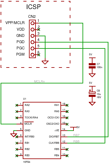
An introduction to the PIC16F84 microcontroller, including connections for an ICSP programmer and a circuit example. The PIC16F84 is an 8-bit microcontroller from Microchip Technology, widely utilized in various embedded applications due to its versatility and ease of use. It...
The transmitting signal can be picked up by any FM radio receiver. Most often used in cars. The problem with most FM transmitters is that they have very weak signals and short transmitting ranges. Some units are so poor...
This circuit is designed for precise centigrade temperature measurement. It features a transmitter section that converts the sensor's output voltage, which is proportional to the measured temperature, into frequency. The output frequency bursts are transmitted through the mains supply...
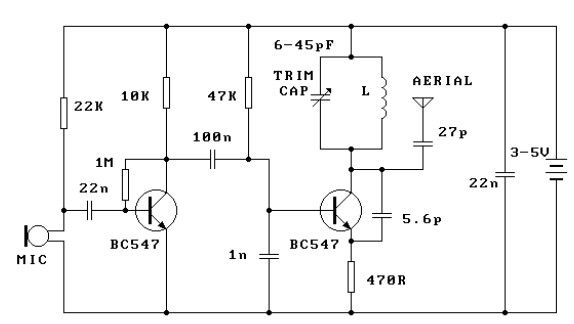
This FM transmitter circuit is very simple and has an acceptable transmission range. The signal transmitted from this FM transmitter circuit can be received at almost 300 meters in open air. The circuit requires a 3-volt operating voltage and...

This transmitter employs a two-stage amplifier configuration using transistors Q1 and Q2 to frequency modulate an NE555 timer, which is set up as a voltage-controlled oscillator (VCO) operating at approximately 50 kHz. The resulting frequency-modulated pulse train is transformed...