
300m fm transmitter circuit design project
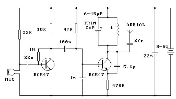
This FM transmitter circuit operates efficiently at a low voltage of 3 volts and is designed for simplicity and ease of assembly. The core component of the circuit is the oscillator, which generates the FM signal. The oscillator is typically built around a transistor that amplifies the oscillations produced by the LC circuit formed by the inductor (coil) and the capacitor. The inductance of the coil and the capacitance of the capacitor determine the frequency of the oscillation, which can be adjusted to any frequency within the FM band.
To ensure optimal performance, it is crucial to maintain a proper distance between the coils after soldering. This prevents unwanted coupling that can lead to instability in the frequency output. The option to use a fixed capacitor allows for basic functionality, but the inclusion of a variable capacitor provides enhanced tuning capabilities, allowing the user to fine-tune the frequency more accurately.
The circuit's effective range of approximately 300 meters in open air makes it suitable for various applications, such as low-power broadcasting or personal projects. For optimal transmission, an appropriate antenna must be connected to the aerial point. The length of the antenna is critical; at a frequency of 100 MHz, a half-wavelength antenna should measure 150 cm, while a quarter-wavelength antenna should measure 75 cm. The antenna's length affects the efficiency of the signal transmission, and adjustments may be needed based on the specific environment in which the transmitter operates.
Overall, this FM transmitter circuit serves as a practical example of basic RF (radio frequency) design principles, providing a foundation for further exploration into wireless communication technologies.This fm transmitter circuit is very simple and it has a acceptable transmission. The signal transited from this fm transmitter circuit can be received at almost 300 meters in open air. The circuit require a 3volts operating voltage and can be tuned anywhere in the FM band. After the coil in soldered into place spread the coils apart about 0. 5 to 1mm so that they are not touching. If you don`t have a trim cap you can use a fixed value capacitor and you can vary the TX frequency by adjusting the spacing of the coils or placing a small piece of ferrite inside the coil, but the better way to change the transmission frequency is to use a variable capacitor. Connect a half or quarter wavelength antenna (length of wire) to the aerial point. At an FM frequency of 100 MHz these lengths are 150 cm and 75 cm respectively. 🔗 External reference
Related Circuits
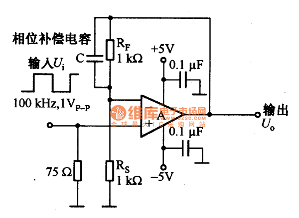
The current feedback operational amplifier maintains a consistent bandwidth even when the open-loop gain is altered. This characteristic makes it particularly suitable for applications in video signal amplification and the driving circuits of video cables. The accompanying diagram illustrates...
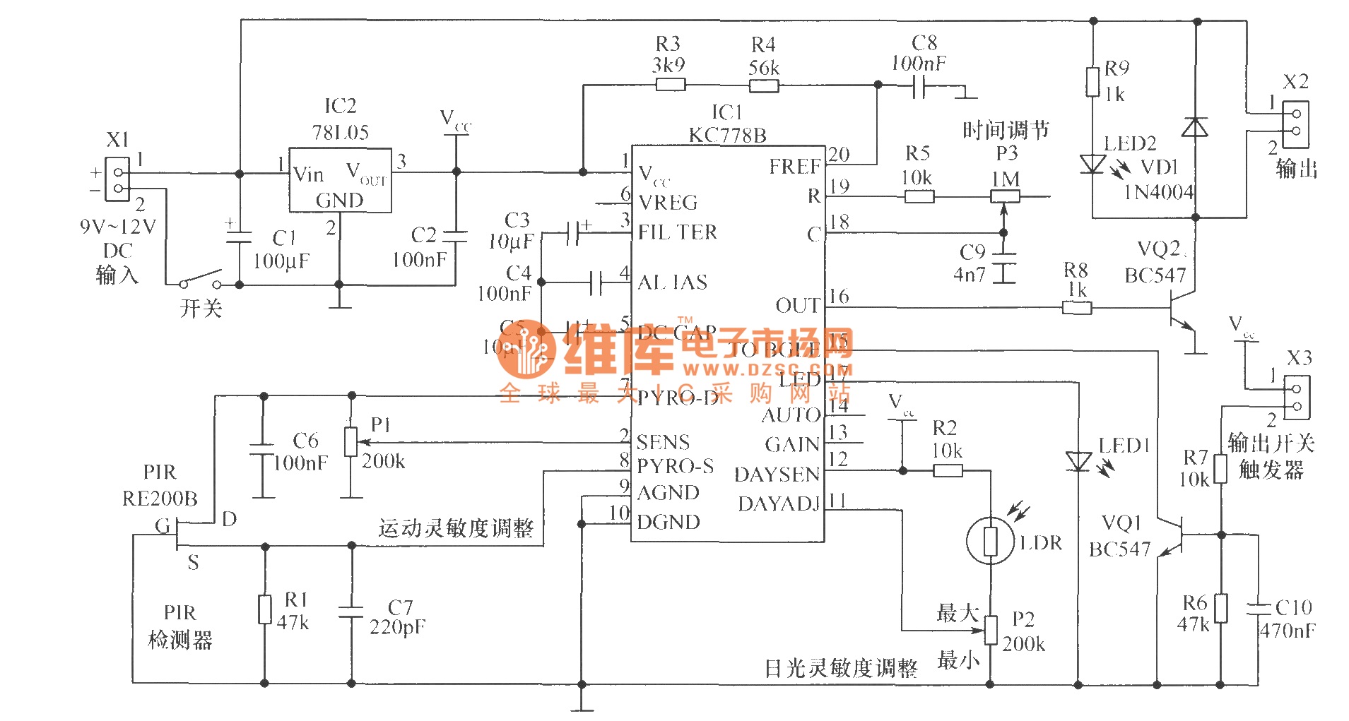
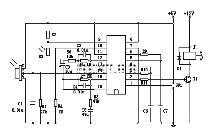
The core component of the motion detection circuit is the motion detection chip IC1 (KC778B). The signal frequency from the PIR sensor is low, ranging from 0.1Hz to 10Hz, while the bandwidth is quite broad, which the chip will...
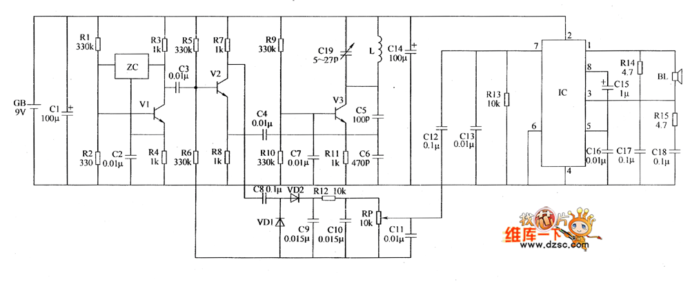
The metal detector circuit includes a fixed frequency oscillator, mixer, detector, detection oscillator, and power amplifier circuit. The fixed frequency oscillator circuit is composed of a ceramic filter (ZC), transistor (V1), resistors (R1 to R4), capacitor (C2), and other...
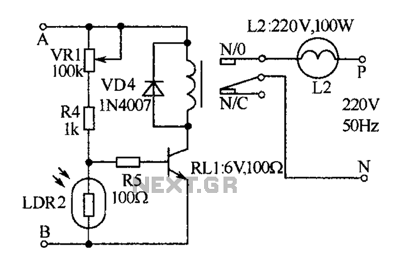
The receiver, as depicted in the figure, assists patients in avoiding missed audio signals during the daytime. The receiver operates independently, and the lighting will automatically turn off. At night, the lighting signal receiver activates simultaneously with the patient's...
The BISS0001 is a high-performance integrated circuit designed for sensor signal processing. When combined with pyroelectric infrared sensors and a minimal number of external components, it forms a passive pyroelectric infrared switch. This device can automatically and quickly activate...
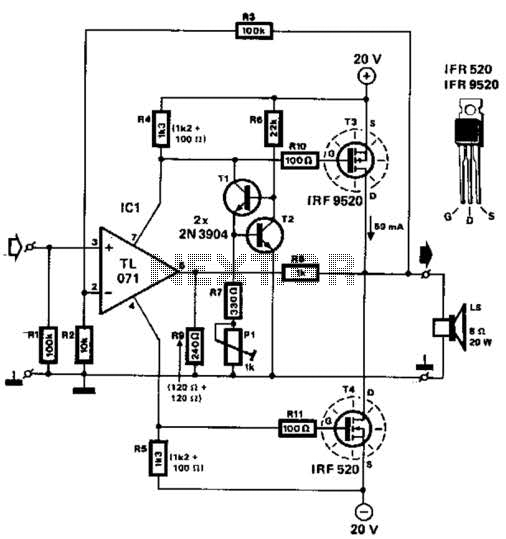
Two complementary MOSFETs are utilized to deliver 20 W into an 8-ohm load. A TL071 operational amplifier serves as the input amplifier. The MOSFETs must be equipped with a heatsink that has a thermal resistance of better than 5...