
Fm Light-Beam Transmitter Circuit

The circuit begins with the NE555 timer configured in astable mode to function as a VCO. The frequency of the output signal can be adjusted by varying the resistors and capacitors connected to the timer. The two-stage amplifier, comprising Q1 and Q2, amplifies the modulating signal before it is fed into the NE555 timer. This ensures that the modulation is strong enough to produce a detectable output at the desired frequency.
Transistors Q1 and Q2 are typically configured in a common-emitter arrangement, providing both voltage gain and current gain. The output from the second stage is connected to the control voltage input of the NE555, allowing for effective frequency modulation. The modulation index can be adjusted by changing the amplitude of the input signal, which directly influences the deviation of the carrier frequency.
The output from the NE555 is a pulse train that varies in frequency based on the modulating signal. This pulse train is then utilized to drive a series of light-emitting diodes (LED1 to LED4). Transistors Q3 and Q4 serve as drivers for the LEDs, allowing them to handle higher current levels than what the NE555 can provide directly. This configuration ensures that the LEDs can operate efficiently and produce a visible light output.
The entire assembly is suitable for applications in optical communication systems, where the modulated light pulses can be transmitted over distances and detected by photodetectors. The design can be further enhanced by incorporating additional stages for improved modulation depth or by using different types of LEDs for varying wavelengths of light. This transmitter uses two-stage amplifier Q1/Q2 to frequency modulate an NE555 (configured as a VCO) operating at about 50 kHz. The resultant FM-modulated pulse train is converted to light pulses via LED1 through LED4, driven by Q3 and Q4. 🔗 External reference
Related Circuits
This flash circuit is a typical camera flash. This flash circuit functions as a high-voltage power supply for camera flash units, enabling the rapid discharge of energy to produce a bright flash of light. The primary components of a typical...
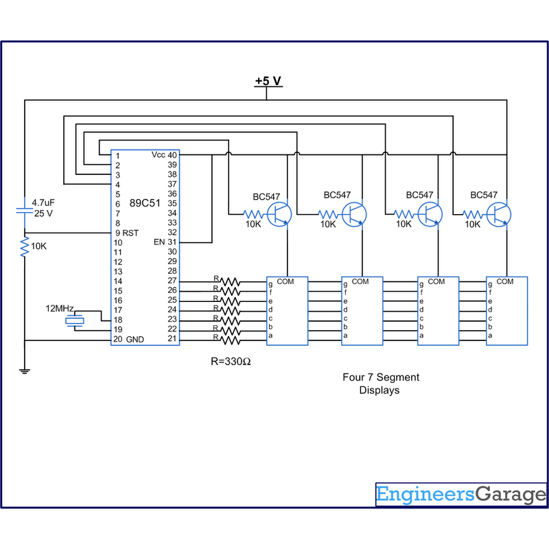
A digital clock displays time in a digital format. The circuit outlined here shows the time with double-digit minutes and two digits for seconds across four seven-segment displays. The segments of the displays are interconnected with the 8051 microcontroller...
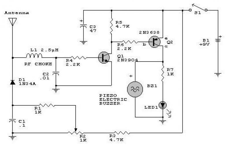
This circuit responds to RF signals below the standard broadcast band up to over 500 MHz and provides both visual and audible indications when an RF signal is detected. By adjusting the bias of diode D2 with the R2...
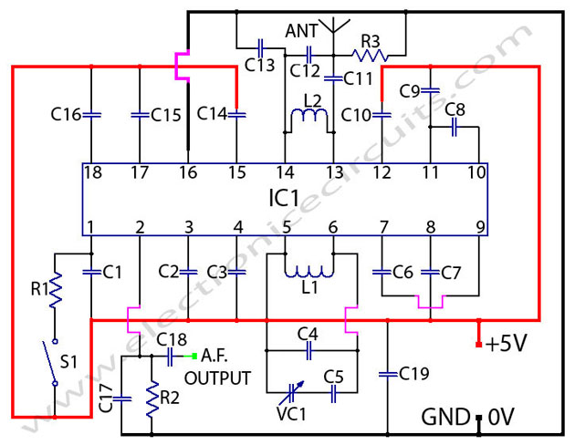
The TDA7000 is a monolithic integrated circuit designed for mono FM portable radios or receivers, emphasizing minimal peripheral components for compact size and cost-effectiveness. This integrated circuit features a Frequency-Locked-Loop (FLL) system with an intermediate frequency of 70 kHz....
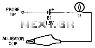
The continuity tester consists of a battery and a lamp connected in series, with one end of the circuit terminated with an alligator clip and the other end connected to the probe tip. The continuity tester is a fundamental...
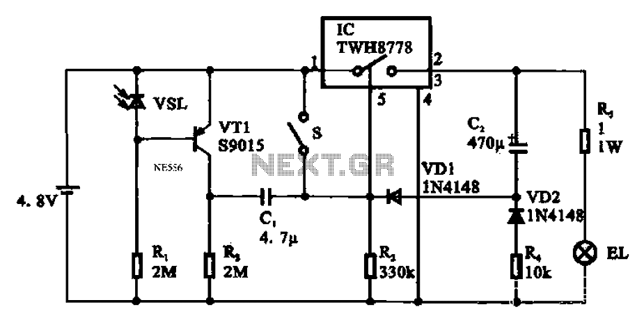
Automatic emergency lamp circuit featuring an electronic switch integrated circuit. This circuit is designed for automatic emergency lighting. The system operates based on ambient light conditions; when light levels are low at night, the circuit activates the emergency lamp....
Warning: include(partials/cookie-banner.php): Failed to open stream: Permission denied in /var/www/html/nextgr/view-circuit.php on line 713
Warning: include(): Failed opening 'partials/cookie-banner.php' for inclusion (include_path='.:/usr/share/php') in /var/www/html/nextgr/view-circuit.php on line 713