
50W Offline Switching Power Supply

The 50W offline switching power supply circuit is designed for efficient power conversion, utilizing MOSFETs to handle different AC input voltages. The choice of BUZ80A/IXTP4N8 and GE IRF823 ensures compatibility with both 220V and 110V AC inputs, respectively, allowing for versatile applications in various regions. The output specification of 5VDC at 10A is suitable for powering a variety of electronic devices, ensuring stable performance under load.
The integration of the STK4036II audio amplifier circuit into the design highlights an emphasis on audio fidelity and thermal management. The compact design of the STK4036II allows it to fit into slim audio systems while maintaining high performance. The use of a heatsink is crucial in this setup, as it helps manage the thermal output, ensuring the IC operates within safe temperatures during extended use.
The TDA7294 amplifier circuit further enhances the audio capabilities, providing a high-quality class AB amplification solution. This IC is particularly well-suited for high-fidelity applications, where low distortion and noise are critical for sound quality. Its ability to deliver substantial power into different load impedances makes it a versatile choice for audio engineers.
The TDA1514A serves as another option for audio amplification, emphasizing its suitability for various audio applications, including consumer electronics. Its design is optimized for high performance, making it a reliable choice for audio systems that demand quality output.
Finally, the STK-1050 power amplifier circuit is noteworthy for its design simplicity, eliminating the need for external emitter resistors, which streamlines the circuit layout and enhances reliability. The optimized emitter resistor values contribute to improved performance characteristics, allowing for lower supply voltage requirements while maintaining efficient operation.
Overall, this comprehensive circuit design showcases a blend of power supply and audio amplification technologies, catering to diverse electronic applications with an emphasis on efficiency, performance, and reliability.The following diagram is the 50W offline switching power supply circuit design. The circuit powered by a MOSFET. BUZ80A/IXTP4N8 for 220V AC voltage input and GE IRF823 for 110V AC input voltage. The output will be 5VDC with electric current up to 10A. The schematic diagram: Component list: The schematic shows a 50-W power supply. Here the 50W AF power amplifier circuit powered with single IC STK4036II. Use heatsink to prevent overheating on the IC. STK4036II features: Compact package for thin-type audio sets Member of pin-compatible series with outputs of 20 to 200W Easy heatsink design to disperse heat generated in thintype stereo sets Constant-current circuit. This is a great audio amplifier circuit based on single power IC TDA7294. TDA7294 is intended for use as a high quality audio class AB amplifier in hi-fi applications. It has very low noise and distortion, wide bandwidth and good output current capability, enabling it to supply high power into both 4 © and 8 © loads.
. Here the another amplifier circuit with single power IC from Phillips, TDA1514A. This is a hi-fi power amplifier circuit with 50W power output. The TDA1514A integrated circuit is a hi-fi power amplifier for use as a building block in radio, tv and other audio applications. The high performance of the IC meets the requirements of. This is a high output power amplifier based on power amplifier IC STK-1050. STK-1050 Features: Does not require externally connected emitter resistors. Values of emitter resistors have carefully been reviewed to provide superior characteristics. Better supply voltage utilization permits designing power supply voltage that are about 0. 7V (for RL=4ohms) lower than those required for previous. 🔗 External reference
Related Circuits

Each of these ways have their own advantages and disadvantages. The multiple transformer way is easy to start small and work up to only as many power supplies as you need. It does, however, get more expensive as the...
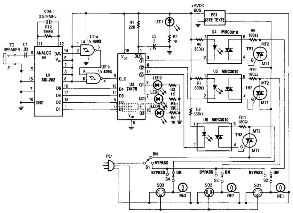
Tones from the DTMF on the telephone line are detected by U1. When a valid tone is received, pin 14 (D More: AV) of U1 produces a positive pulse that is used to drive NAND gates U2A and U2B,...

Numerous miniature FM transmitter bug circuits are available online; however, this particular design is distinctive as it operates entirely on solar power, eliminating the need for a battery. The transmitter will function as long as sunlight is incident on...
The losses in a bridge rectifier can become significant when rectifying low voltages. The voltage drop across the bridge is approximately 1.5 V, which constitutes about 25% loss with an input voltage of 6V. This loss can be reduced...
This power supply is based on the LM317 Variable Regulator. The input of the regulator needs to be around 28 Volts DC and it will output a DC voltage from 1.25vdc to 25 vdc. To adjust the output voltage...
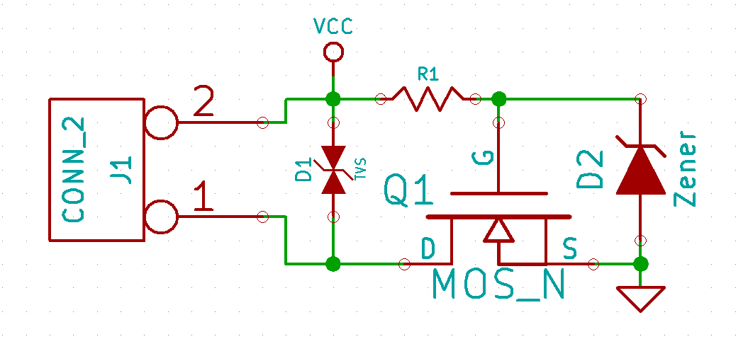
A reverse polarity protection circuit is presented, similar to the one depicted in Figure 2 of SLVA139: Reverse Current/Battery Protection Circuits. The circuit in question is slightly more complex due to the potential input voltage range of 5-40V. Most...