
Telephone-Operated Ac Power Switch
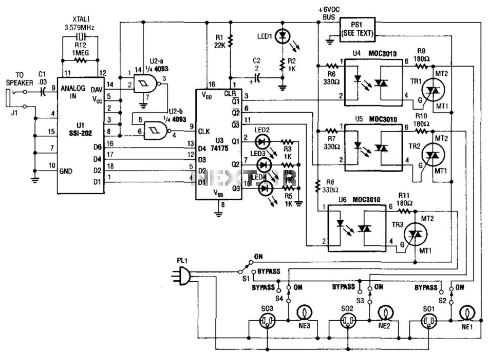
The described circuit utilizes Dual-Tone Multi-Frequency (DTMF) signaling to detect tones from a telephone line. The detection process begins with the integrated circuit U1, which is specifically designed to interpret DTMF signals. Upon receiving a valid tone, the output at pin 14 generates a positive pulse signal. This pulse is then fed into two NAND gates, U2A and U2B, which perform logical operations that further process the signal.
The output from the NAND gates is critical as it triggers the latching mechanism of the Quad-D flip-flop U3. This flip-flop is capable of storing binary data, allowing for the potential decoding of up to 16 bits from the input signals of U1. The Q outputs of U3 provide a digital representation of the received DTMF tones.
To manage the control of external devices, the Q outputs are connected to optoisolators. These components provide electrical isolation between the digital circuitry and the power control elements, ensuring safe operation. The optoisolators drive triacs TR1, TR2, and TR3, which can control high-power loads, such as lights or motors, based on the detected DTMF tones.
The power supply for the circuit, designated as PS1, is a 6-V, 150-mA DC adapter designed to operate from a standard 120 Vac input. This power supply ensures that all components receive the necessary voltage and current for reliable operation.
Overall, this circuit efficiently integrates DTMF tone detection with control mechanisms for external devices, leveraging digital logic and power electronics to achieve its functionality. Tones (from the DTMF) on the telephone line are detected by Ul. When a valid tone is received, pin 14 (D AV) of Ul produces a positive pulse that is used to drive NAND gates U2A and U2B and then to latch binary data from Ul into Quad-D flip-flop U3 (Ul could be decoded into 16 bits, if required). The Q outputs of U3 drive optoisolators that control triacs TR1, TR2, and TR3. PS1 is a 6-V 150-mA dc adapter that operates from 120 Vac. 🔗 External reference
Related Circuits
This circuit illustrates the SSR (Solid State Relay) Power Control Unit Circuit Diagram. Features: The SSR control box supplies the control voltage for the relay. Component: . The SSR Power Control Unit Circuit is designed to provide efficient control of...
The MAX34446 data logger for power supplies is capable of monitoring voltages for overvoltage and undervoltage conditions, as well as overcurrent and overtemperature situations. The device continuously checks user-programmable thresholds. The MAX34446 is an advanced monitoring solution designed for power...
The MC145152-2 synthesizer can be programmed using DIP switches, a diode matrix, or EPROM look-up tables. However, it is now difficult to find, costing around US$30. Modern synthesizers require PIC processors for programming or must remain connected to a...
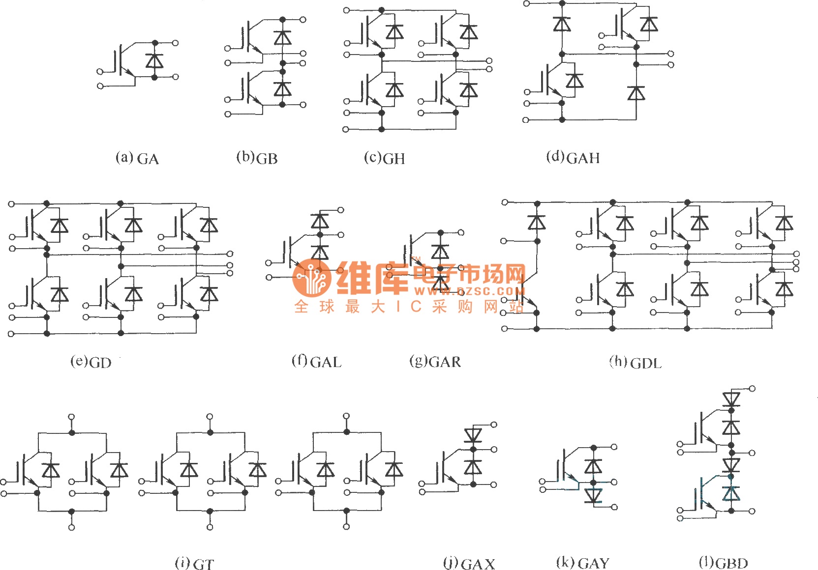
This document describes various electronic modules, including: (a) a single switch module; (b) a two-unit half bridge module; (c) an H bridge (single-phase bridge) module; (d) an asymmetrical H bridge module; (e) a three-phase bridge (six-unit or inverter bridge)...

This power supply circuit is highly stabilized that its output voltage will drop only 0.005% even though the load changes from 0 to 100%. Another excellent capability is that the output voltage will change only by 0.01% if the...
This is a 28VDC to 5VDC switching converter circuit. As a switch-mode voltage regulator, this circuit provides higher efficiency than linear regulator types. The 28VDC to 5VDC switching converter circuit operates by converting a higher voltage direct current (DC) input...