
Dual Tone Sounder Circuit
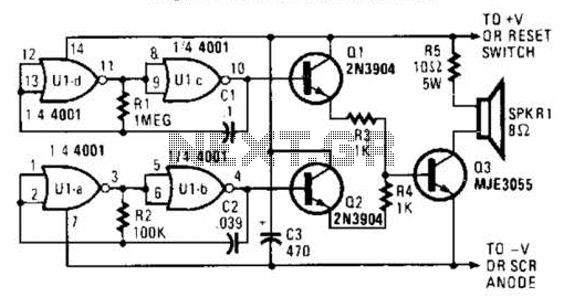
The oscillator frequencies (and consequently the tones they generate) can be modified by adjusting the values of R1 and C7 for the low-frequency oscillator, and R2 and C2 for the high-frequency oscillator. Reducing the values of these components will increase the frequency, while increasing their values will decrease the frequency. The outputs from the two oscillators are fed into separate amplifiers configured as emitter followers, which drive a single power transistor (Q3, an MJE3055). A 10- or 5-ohm resistor, R5, is utilized to limit the current flowing through the speaker and Q3 to a safe level. To enhance the sound output, R5 can be substituted with an additional speaker.
This circuit design is primarily aimed at generating distinct audio tones suitable for alarm applications. The use of a horn-type speaker allows for increased sound projection, making it effective for alerting purposes in various environments. The choice of components, including the CMOS NOR gates and NPN transistors, facilitates the creation of the desired audio frequencies through feedback oscillation.
The oscillator configuration is crucial for achieving the required sound characteristics. By carefully selecting resistor and capacitor values, the designer can fine-tune the output frequencies to meet specific requirements. The integration of emitter follower amplifiers ensures that the signal strength is adequate to drive the power transistor, which in turn powers the speaker without risking damage to the components.
In practical applications, attention must be paid to power management, particularly when utilizing a high-power SCR for driving the sounder. The circuit’s design allows for flexibility in sound output, and the option to replace the current-limiting resistor with an additional speaker provides an opportunity to amplify the sound further, catering to environments where high sound levels are necessary for effective alerting. Overall, this circuit exemplifies a robust solution for alarm systems requiring reliable and powerful audio output. An outside horn-type speaker works best with the circuit. However, such devices require a great deal of power, so this sounder should only be used in alarm circuits where at least a 6-A SCR is used as the sounder driver. A single CMOS 4001 quad 2-input NOR gate, two 2N3904 general- purpose npri transistors, and a single MJE3055 power transistor combine to generate a two-tone output.
Gates Ul-a and Ul-b are configured as a simple feedback oscillator with R2 and C2 setting the oscillator`s frequency. With the values shown, the circuit oscillates at about 500 Hz. Gates Ul-c and Ul-d are connected in a similar oscillator circuit, but they operate at a much lower frequency.
The oscillator frequencies (and thus the tones that they produce) can be altered by increasing or decreasing, the values of Rl and C7] for the low-frequency oscillator and R2 and C2 for the high-frequency oscillator. Decreasing the values of those components will increase the frequency; increasing their values will decrease the frequency.
The two oscillator outputs are connected to separate amplifiers (configured as emitter followers), whose outputs are used to drive a single power transistor (Q3, an MJE3055). 10-, 5-W resistor, R5, is used to limit the current through the speaker and Q3 to a safe level. To boost the sound level, R5 can be replaced with another speaker. 🔗 External reference
Related Circuits

This 555 timer circuit temperature monitoring system project can monitor temperature at up to four points. The system allows for the selection of whether the alarm should be triggered when the temperature increases or decreases, depending on the resistance...
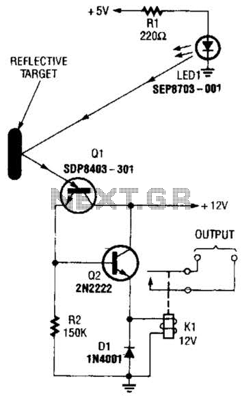
A reflector isolator detects the presence of an object by bouncing light off of it. This technique is useful in circuits that detect when an object is close enough to the sensor. A reflector isolator is a type of optical...
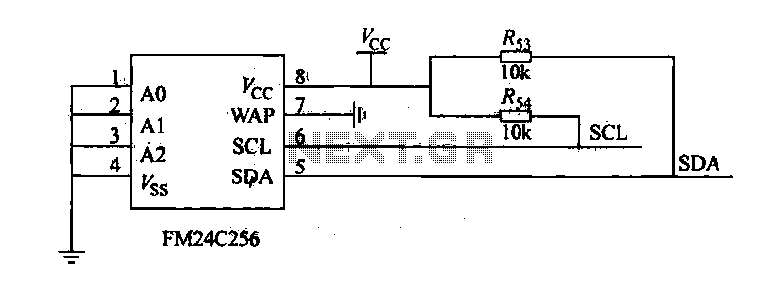
The FM24C256 is utilized as a slave interface circuit in an I2C bus configuration, with the address format specified in Table 27-3. The address pins A2, A1, and A0 are set to low; however, for extended storage capacity, adjustments...
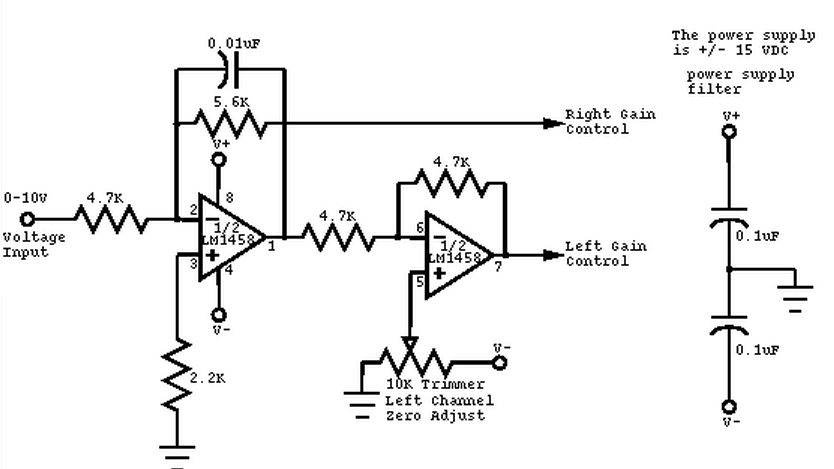
This circuit converts a mono audio signal into a stereo signal that can be panned between the left and right channels using a 0-10V control signal. It is designed for analog synthesizer systems. The circuit operates by taking a single...
Its state is constantly changing, and this change affects the flow of current and voltage, which is visible with the two LEDs. The speed of the LED flasher can be adjusted with potentiometer P1. As an astable multivibrator, the...
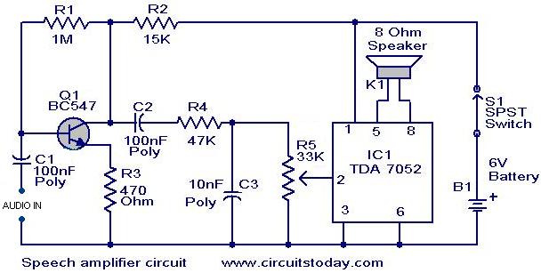
This circuit can be housed within a box containing a speaker to create a convenient microphone amplifier. It is suitable for use by teachers, guides, lecturers, and others in crowded or noisy environments. The design is based on the...