
Musical car reverse horn circuit
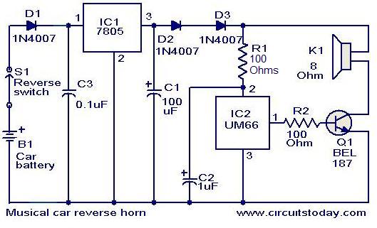
The circuit operates as follows: When the vehicle is shifted into reverse, the reverse gear switch closes, completing the circuit. This action supplies power to the voltage regulator (IC1), which converts the car's battery voltage (typically 12V) down to a stable 5V output. The output from IC1 is then fed to the UM66 (IC2), which is configured to generate a specific musical tone. The diodes D1 and D2 are critical in ensuring that the voltage supplied to the UM66 does not exceed its maximum rating of 4V, thereby protecting the IC from potential damage due to overvoltage.
The transistor T1 serves as an amplifier, enhancing the audio output of the UM66. It is connected to a loudspeaker, which converts the amplified electrical signal back into sound. The choice of components, including the specific voltage regulator and tone generator, is essential for ensuring reliable operation and sound quality. The circuit can be housed in a weatherproof enclosure to protect it from the automotive environment, ensuring durability and longevity.
Overall, this musical horn circuit offers a novel and entertaining alert system for drivers, enhancing safety by providing an audio cue when the vehicle is in reverse.Here is a simple circuit that will produce a musical horn when ever your car is in reverse gear. The circuit uses two ICs for the operation, voltage regulator 7805(IC1) and musical tone generator UM66(IC2). The IC1 reduces the car battery voltage to 5V. The diodes D1 & D2 in combination produces an additional drop of 1. 4 V to give a 3. 6 V supply fo r the UM66. The supply voltage of UM 66 should not be more than 4V. When ever the car is in reverse gear, the reverse gear switch of the car gets activated and the circuit gets connected to the car battery. The UM66 starts playing the music tone. The transistor T1 amplifies the output of UM66 to drive the loudspeaker. 🔗 External reference
Related Circuits
This transmitter emits an FM signal within the 88 to 108 MHz frequency range, featuring a tone of 19 kHz. This tone can activate the FM MPX pilot carrier indicator, allowing interfacing with external devices. L4 is designed for...
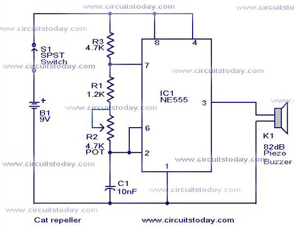
This cat and dog repeller circuit is designed to deter animals from specific areas. The circuit utilizes ultrasonic sound, which is known to provoke a strong response in many animals, particularly cats. The design features an astable multivibrator configuration...
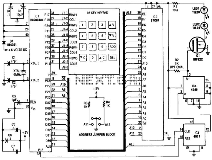
The infrared receiver requires the infrared light to be modulated at 38 kHz, which corresponds to a period of 26 µs. The specifications for the receiver suggested using a 50% duty cycle; however, this configuration did not perform as...
Building circuits to interface an Amiga A1200 to a PC AT/ATX power supply and tower case. To create a reliable interface between an Amiga A1200 and a PC AT/ATX power supply and tower case, it is essential to design a...
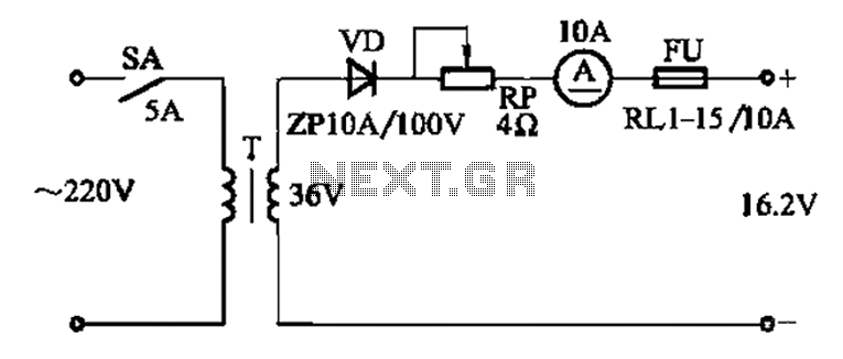
The adjustment potentiometer RP is utilized to modify the charging current. The adjustment potentiometer, designated as RP, serves a critical function in regulating the charging current within an electronic circuit. This component is typically a variable resistor that allows for...

Frequency converter schematic, frequency to voltage converter schematic, frequency to voltage converter using TR, voltage to frequency converter application. A frequency converter is an essential electronic circuit that transforms frequency signals into corresponding voltage levels or vice versa. The frequency...
Warning: include(partials/cookie-banner.php): Failed to open stream: Permission denied in /var/www/html/nextgr/view-circuit.php on line 713
Warning: include(): Failed opening 'partials/cookie-banner.php' for inclusion (include_path='.:/usr/share/php') in /var/www/html/nextgr/view-circuit.php on line 713