
Asia ultrasonic remote control circuit

The operational principle of the sub-circuit involves the ultrasonic whistle activating the ultrasonic sensor (B), which receives the ultrasonic signal and converts it into an electrical signal. This signal is amplified by transistor (VT1) and triggers the flip-flop via transistor (VT2), causing it to switch states. When the ultrasonic whistle is not pinched, the flip-flop output remains low, keeping transistor (VT5) off, and relay (K) remains in its release state. Consequently, the LED does not illuminate, and the connected load (electrical equipment) remains inactive. Upon pinching the ultrasonic whistle, the flip-flop transitions to the opposite state, yielding a high output that activates transistor (VT5). This conduction energizes relay (K), closing its normally open contact and supplying power to the load, while the LED lights up to indicate that the ultrasonic remote control switch is in the ON state. When the ultrasonic whistle is pinched again, transistor (VT5) turns off, relay (K) releases, cutting off the voltage to the load, and the LED turns off, indicating that the remote control switch is now in the OFF state.
This circuit design effectively utilizes ultrasonic technology for remote switching applications, providing a practical solution for controlling various electrical devices wirelessly. The integration of components ensures reliable operation, while the flip-flop mechanism allows for stable state changes based on ultrasonic signal detection. Asia ultrasonic remote control switch This example describes using gas pressure bisulfite ultrasound flute (made of rubber, there are olive and flat round) control. When using ultrasound Yong Shounie about Asia flute, remote control switch that is turned on; then pinch Asia ultrasonic whistle, the switch is closed. The Asia ultrasonic remote control switch can be used to control lights, exhaust fans and some small electrical equipment.
(1) The composition of the sub-circuit ultrasonic remote control switch circuit from the power circuit, sub ultrasound control circuit, flip flop and control the implementation of circuit composed of the power circuit by the fuse FU, step-down capacitor Cl, resistors Ri, rectifier diode VD1, VD2, filter capacitor C2 and Zener diode vs composition. The control circuit by a sub-sub-ultrasonic ultrasonic transducer B, transistors VT1, VT2, diode VD3, resistors R2, R3, inductor L and the electric vessel G, C5 components.
By the flip-flop transistors VT3, VT4, diode VD4, VD5, resistors R4, R, and a capacitor C5, CH composition. Executed by the control circuit transistor VT5, resistors Rio, Ru, a light emitting diode LED and relay K composition.
AC 220V voltage by CJ Buck, VD2 rectifier, G filter and vS regulator after VD1 and produce 9V DC voltage supply Yachao sound control circuit, flip flop and control the implementation of circuit. (2) sub-circuit principle When Yong Shounie about ultrasonic whistle, the sub-ultrasonic sensor B will receive the ultrasonic signal is converted into an electrical sub, the signal by the VT1, after VTZ amplified to trigger the flip-flop, it from one state to the other state.
If the sub-pinching when no ultrasonic whistle, the flip-flop output low, the VT5 end, K is the release state. LED is not lit, output xs yuan gross output electric fishing Block J, the load (electrical equipment) does not work.
When pinch dish ultrasonic whistle after the flip-flop is converted into another state, the output high, so VT5 conduction. K pull its normally open contact connected, supplies power to the load through xs, while LED lights indicating that the sub-ultrasonic remote control switch in the ON state.
Then pinch a Lower ultrasonic whistle, then VT5 end, K release, voltage xs disappears, LED goes out, indicating that the remote control switch is turned off.
Related Circuits
This is a non-contact power regulator circuit designed for a light load. By adjusting a 150kΩ potentiometer, phase shift can be achieved, and a trigger voltage is applied to the gate of a bidirectional thyristor through a bidirectional trigger...
The main ΣΔ loop operates in steady state and is fully controlled by summing comparator Q2. This comparator amplifies the ripples of the sensed inductor current and output voltage with gains KI and KV, respectively, to generate an internal...
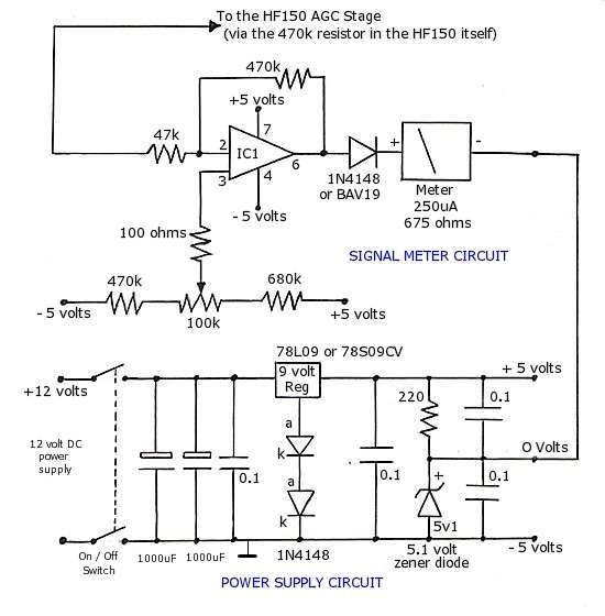
The operational amplifier (op-amp) used in the signal meter circuit is the TL061. The LF351 can also be used interchangeably, as it has the same pin layout. For those using a TL062 or similar models, the differing pin configurations...
Carrier current remote control device or intercom circuit diagram as follows: The circuit diagram for a carrier current remote control device or intercom system typically involves the use of carrier current technology to transmit audio signals over existing electrical...
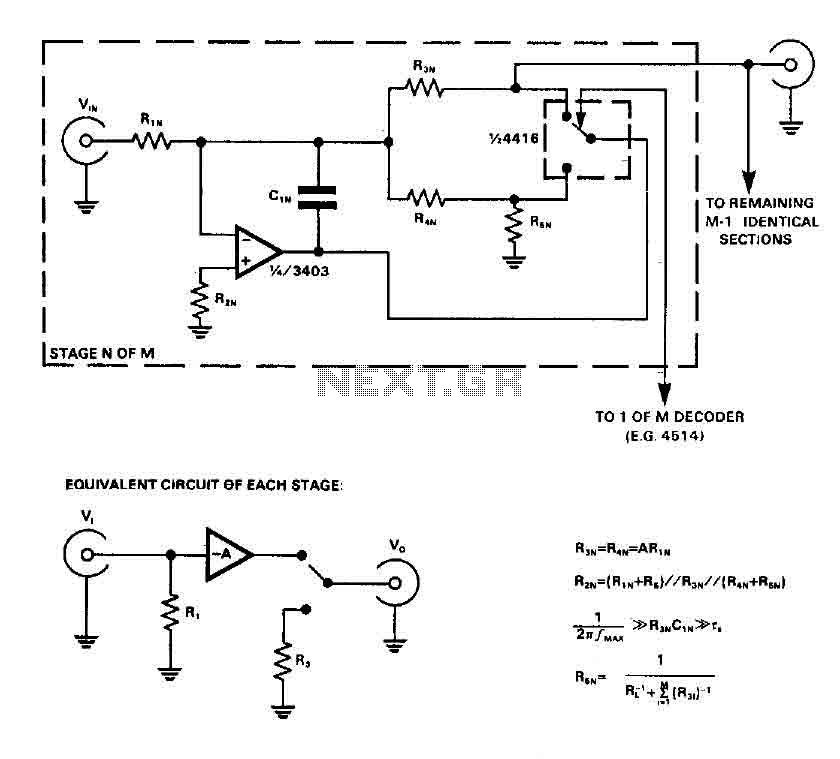
CMOS switches are utilized to select entries in audio circuits. While these switches can introduce unacceptable levels of distortion, incorporating them into the feedback network of an operational amplifier (op amp) can effectively minimize this distortion. The circuit employs...
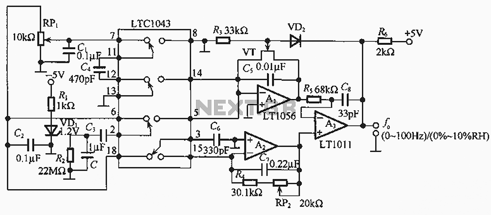
The humidity/frequency conversion circuit operates similarly to the previously mentioned humidity sensors. At a humidity level of 76%, the equivalent capacitance is 500 pF, with a capacitive relative humidity variation rate of +1.7 pF/%. The circuit includes an integrating...