
555 alarm doorbell and lighting controller circuit
The controller circuit features a Hall effect sensor (DN838) that detects magnetic fields and can be activated by a magnet. When the sensor is triggered, it sends a signal to the astable multivibrator, which generates a continuous square wave output. The 555 timer in astable mode is configured with resistors and capacitors, determining the frequency and duty cycle of the output signal.
In automatic door opening applications, the Hall sensor can be positioned near a door frame, and when a user approaches with a magnet (e.g., on a key fob), the door can be programmed to open automatically. For delay alarms, the output from the 555 timer can be used to trigger an audible alarm after a predetermined time, providing a warning before activation.
The circuit can also control lighting systems by using the astable multivibrator to turn lights on and off automatically, based on the presence of a magnetic field detected by the Hall sensor. This feature is beneficial for energy-saving applications. Additionally, the circuit can function as a doorbell, where the Hall sensor detects the presence of a visitor and activates a chime or buzzer.
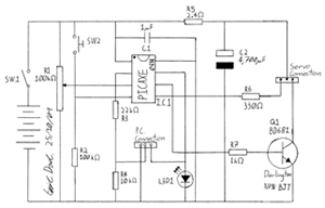
Overall, the combination of the Hall integrated circuit and the astable multivibrator provides a versatile and efficient solution for various automation tasks in residential and commercial settings.As the figure 15-24 shows, the controller circuit is composed of the switch type Hall integrated circuit DN838 and the astable multivibrator (composed of the 555), this circuit can be used in wide range of applications such as the automatic door opening, automatic delay alarm, automatically turns off the lights and also it can be used as the doorbell. The a.. 🔗 External reference
Related Circuits
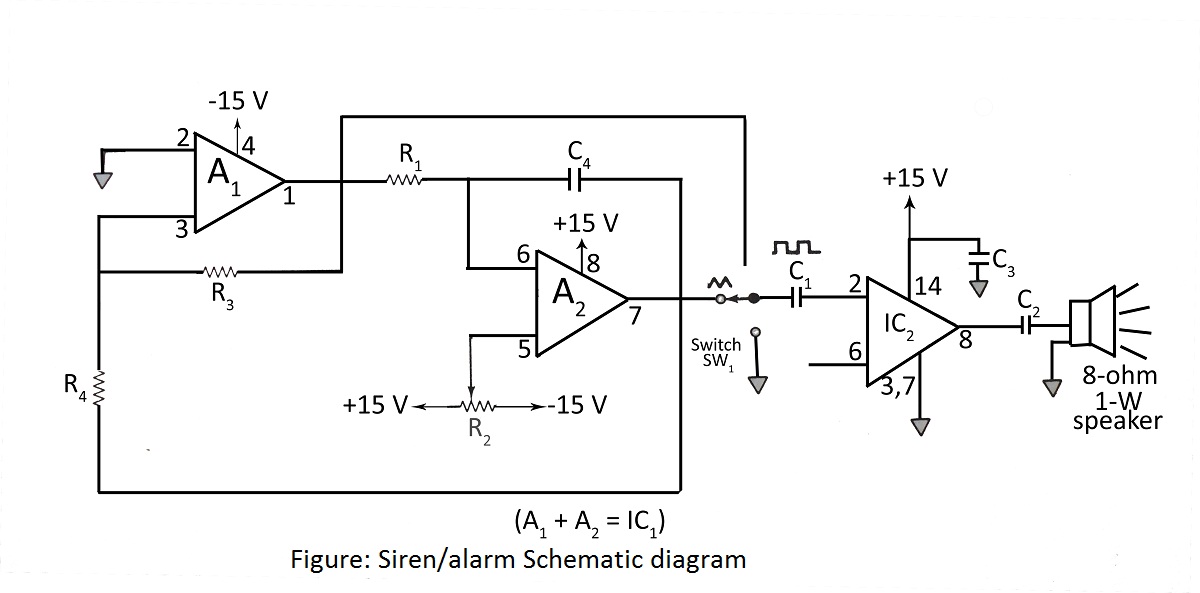
A simple siren or alarm circuit utilizing the MC1458 dual op-amp and the audio power amplifier LM380 is presented. The circuit diagram includes various configurations for sirens, doorbells, and alarm systems, along with a comprehensive parts list. The circuit operates...
This is a voltage converter designed to output a voltage range of ±1.25 to ±30V from an input voltage of ±35V. A three-terminal voltage regulator is utilized to achieve the desired voltage transformation in this unit. The voltage converter employs...
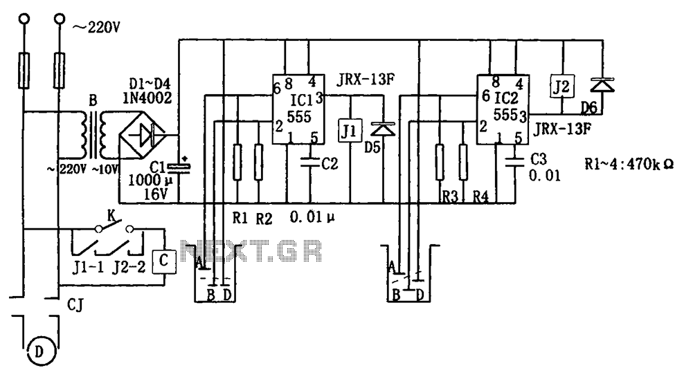
The level control circuit comprises a step-down rectifier circuit, a trigger circuit utilizing two 555 timer ICs (IC1 and IC2), and a relay control circuit. The rectifier circuit is responsible for providing the necessary DC voltage for the flip-flop...
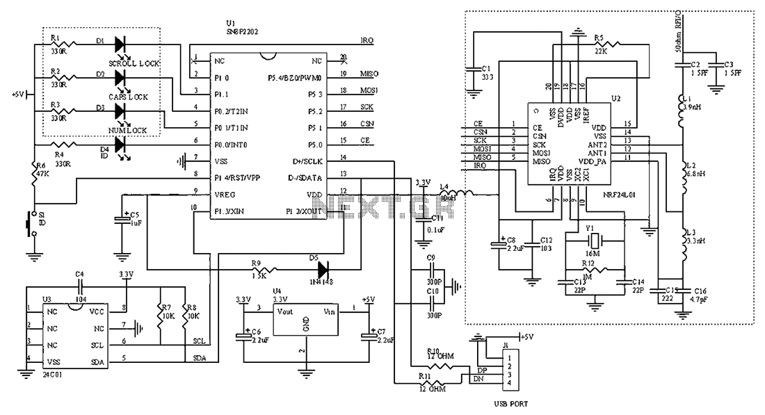
The circuit diagram for the receiving portion of a 2.4 GHz wireless keyboard is presented below. The 2.4 GHz wireless keyboard receiving circuit typically consists of several key components that work together to receive and process signals transmitted from the...
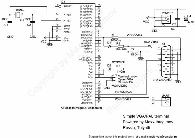
To prevent image distortion when receiving data via UART for VGA, it is advisable to conduct data exchange with the terminal approximately 300-600 microseconds after the vertical synchronization (VSYNC) signal. In a VGA system, the synchronization signals are crucial for...
This project involves creating a programmable camera controller using basic hand tools and a digital camera. By utilizing components that are commonly found at home, the overall costs can be minimized. A servomotor can be repurposed from a radio-controlled...
Warning: include(partials/cookie-banner.php): Failed to open stream: Permission denied in /var/www/html/nextgr/view-circuit.php on line 713
Warning: include(): Failed opening 'partials/cookie-banner.php' for inclusion (include_path='.:/usr/share/php') in /var/www/html/nextgr/view-circuit.php on line 713