
Level 555 a control circuit diagram
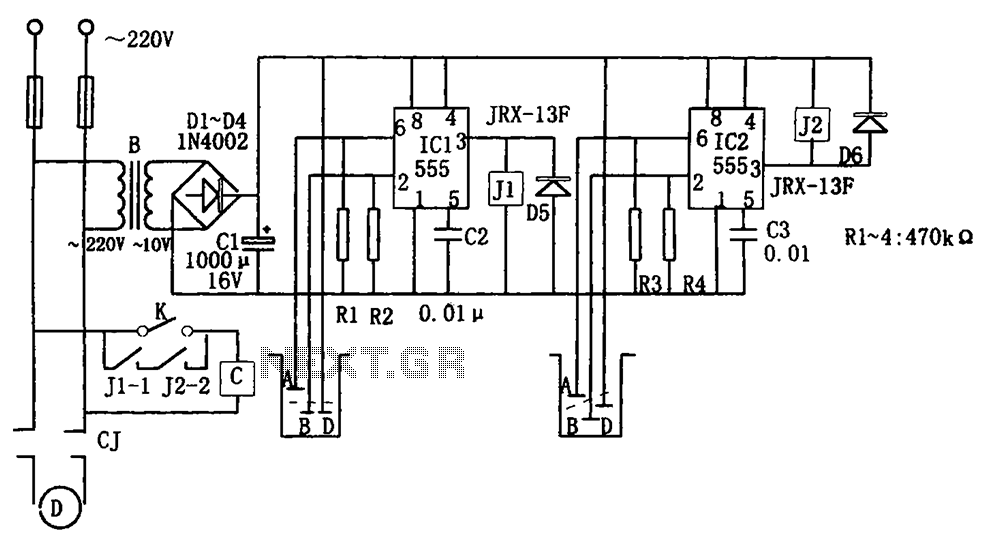
The level control circuit is designed to provide an efficient and automated solution for managing water levels in a tower and well system. The step-down rectifier circuit converts AC voltage to a stable DC voltage, ensuring that both timer ICs operate effectively. The 555 timer ICs are configured as flip-flops, which allow for precise control of the water pump based on the input from the water level probes.
In operation, the system continuously monitors the water levels through the probes. When the water level in the tower drops below a predetermined threshold, the circuit activates the pump, ensuring that the water level is maintained. Conversely, when the water level reaches the upper threshold, the circuit deactivates the pump to prevent overflow. The relay control circuit serves as a switching mechanism that connects or disconnects power to the pump based on the outputs from the timer ICs.
The positioning of probes B, D, and A is critical for the accurate functioning of the system. Proper calibration of these probes ensures that the water levels are monitored effectively, allowing for timely activation and deactivation of the pump. Additionally, the use of a relay provides electrical isolation between the control circuit and the high-power motor, enhancing safety and reliability.
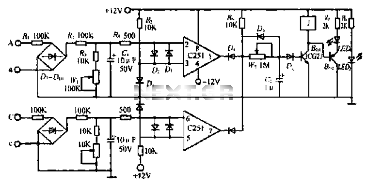
Overall, this level control circuit is an effective solution for automated water management, utilizing widely available components to achieve reliable operation in various applications. As shown for the level control circuit. The control circuit consists of step-down rectifier circuit, trigger circuit 555 (IC1, IC2), relay control circuit. Where the buck recti fier circuit of the entire control circuit to provide the DC voltage corresponding to the flip-flop IC1 low water tower water pump control circuit, triggering circuit IC2 corresponding to the high-water wells to pump water for the control circuit.When the water level inside the water tower probe B, D tower above the water line, IC1 pin is ground level, so that IC1 be set, high pin output relay J1 pull, contact J1- 1 is closed, because the motor is energized and pumping operation performed pumping; when the water level rises to probe a, corresponding IC1 is reset, low output enable J1 release, contact J1-1 disconnect power pumps stopped, thus the water tower to achieve automatic control. Well placed in the probe B, D, under normal circumstances, should a certain depth below the water surface, so IC2 (555) by 2 feet high and reset, low output enable pin J2 pull, touch point J2-2 is closed.
When leaving due to continuous pumping B, D EXPLORATION high in the water, IC2 occur due feet set low, high output enable pin J2 release, contact J2-2 disconnect the motor off electricity stopped, thus avoiding motor idling, while the water level of wells for testing.
Related Circuits
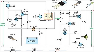
This circuit is designed to switch power to a Peltier cooler in a vehicle. Power is supplied to the load from the vehicle's battery when the ignition switch is on and from an SLA auxiliary battery when the ignition...
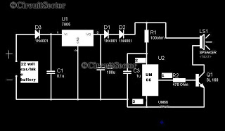
A simple musical horn circuit designed for use in cars or motorcycles can be connected to the 12V battery of any vehicle. This circuit is commonly utilized as a reverse musical horn. It employs the low-cost musical integrated circuit...
Generating long delays of several hours can be achieved using a low-frequency oscillator and a binary counter. A single Schmitt Trigger inverter stage (1/6 of 74HC14) functions as a square wave oscillator, producing a low frequency of approximately 0.5...
This circuit gradually switches the internal lights of a car on and off. The delay time can be adjusted by changing the values of the 10k and 4.7M resistors, as well as the capacitor. The circuit operates by utilizing a...
Circle i represents a two-phase grid connection line for an AC technology turbine shed, which consists of two lines. A voltage is generated between Ri through a Buck converter, with components R1 and R3 dividing the output. The sampled...
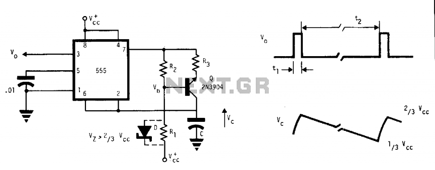
This free-running multivibrator utilizes an external current sink to discharge the timing capacitor, C. As a result, the interval can easily be 1000 times the pulse duration, t1, which defines a positive output. The voltage across the capacitor, V,...