
2.4G wireless keyboard receiver part of the circuit
The 2.4 GHz wireless keyboard receiving circuit typically consists of several key components that work together to receive and process signals transmitted from the keyboard. The main components include an antenna, a radio frequency (RF) receiver module, a microcontroller, and associated passive components such as resistors and capacitors.
The antenna is responsible for capturing the RF signals transmitted by the wireless keyboard. It is designed to operate efficiently at 2.4 GHz, ensuring optimal reception of the signals. The RF receiver module demodulates the incoming signals, converting them from radio frequency to baseband signals that can be processed by the microcontroller.
The microcontroller serves as the central processing unit of the receiving circuit. It interprets the demodulated signals, translating them into commands that correspond to keystrokes made on the keyboard. The microcontroller may also include firmware that manages the communication protocol and handles any error correction necessary for reliable data transmission.
Additionally, passive components such as capacitors and resistors are used to filter noise and stabilize the power supply to the RF receiver and microcontroller. Proper design of the power supply circuit is crucial to ensure that the components operate within their specified voltage and current ranges, thereby enhancing the overall performance and reliability of the wireless keyboard system.
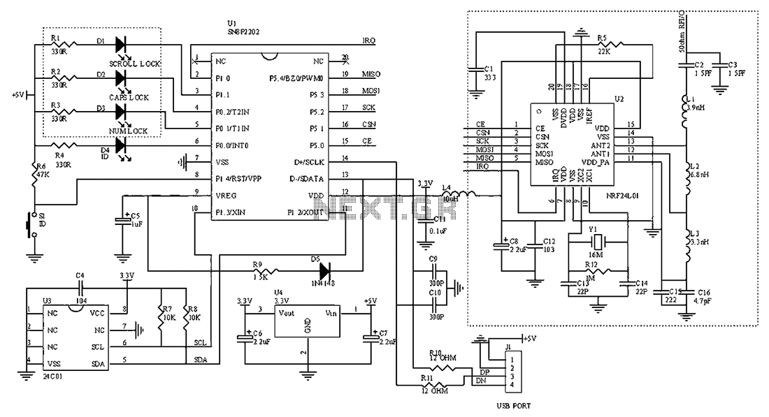
In summary, the 2.4 GHz wireless keyboard receiving circuit integrates an antenna, RF receiver, microcontroller, and passive components to effectively receive and process wireless signals, enabling seamless communication between the keyboard and the host device. This design is essential for achieving the desired user experience in wireless keyboard applications.2.4G wireless keyboard receiving portion circuit diagram as follows:
Related Circuits
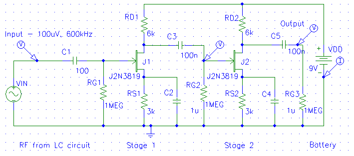
The diagrams below illustrate the development of a simple modular radio receiver based entirely on circuits and devices studied during the Part IA course on Linear Circuits and Devices. This receiver may not revolutionize the market; however, it aims...
The crystal-controlled SoftRock receivers developed by Tony Parks (KB9YIG) have played a significant role in introducing many individuals to Software Defined Radio (SDR). For those who prefer not to be limited to a single frequency, the SoftRock Ensemble receivers...
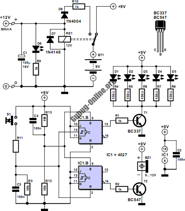
This circuit is designed to control the mains pulse. The pulser's purpose is to switch the mains voltage on and off at intervals ranging from just under one second to a maximum of ten minutes. This functionality is beneficial...
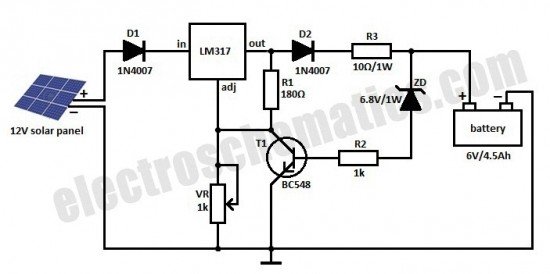
This is a solar charger circuit designed to charge Lead Acid or Ni-Cd batteries using solar energy. The circuit captures solar energy to charge the batteries. The solar charger circuit typically consists of several key components, including a solar panel,...
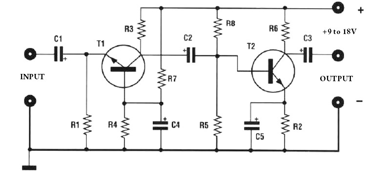
The amplification of this preamplifier is very high. To reduce the amplification, a trimmer resistor R3 in series with a value of 100 ohms should be used. The system can be powered by a voltage ranging from 9 to...
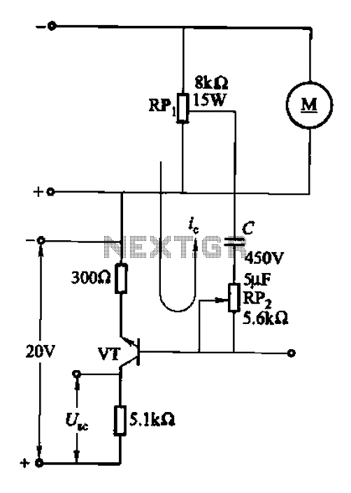
After integrating the negative feedback circuit, the adjustment object and inertial measurement feedback link are susceptible to oscillations. To address this, a voltage differential or speed differential circuit is employed to minimize or eliminate these oscillations, serving as a...