
555 Am TransmitterCircuits
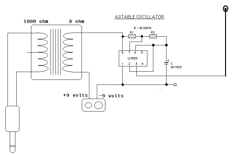
The ICM7555 is a low-power CMOS version of the classic 555 timer, which can be configured in various modes including astable, monostable, and bistable operations. In the context of an AM radio transmitter, the 555 timer can be used to generate a modulated signal suitable for transmission.
A typical AM radio transmitter circuit using a 555 timer consists of several key components: the 555 timer itself, an oscillator circuit, a modulating signal input (which could be audio), and an output stage that includes an RF amplifier and an antenna.
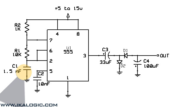
For a simple AM transmitter using a single ICM7555, the timer can be configured in astable mode to generate a carrier frequency. The frequency can be set by selecting appropriate resistor and capacitor values connected to the 555 timer. The output from the timer can be fed into a transistor amplifier stage, which increases the power of the signal to drive an antenna for transmission.
If utilizing two ICM7555 timers, one can serve as the modulator while the other functions as the oscillator. The first timer generates the carrier wave, and the second timer can modulate this signal with an audio input. The modulated output can then be amplified and transmitted via an antenna.
It is essential to ensure that the output frequency falls within the AM radio band (typically 530 kHz to 1700 kHz) for proper reception. The circuit should also include appropriate filtering to eliminate unwanted harmonics and ensure a clean signal is transmitted.
When designing the circuit, attention must be paid to power supply decoupling, component ratings, and antenna matching to optimize performance and ensure compliance with local regulations regarding radio frequency transmissions.I have two ICM7555 CMOS 555 timers, and I was wondering if anyone has any good am radio transmitter circuits that incorporate two (or one!) 555 timers.. 🔗 External reference
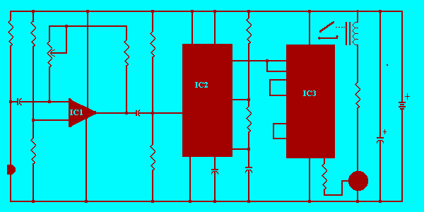
Related Circuits
A single hand clap will be picked up by the electric mic which is coupled through C1 into the op amp IC1. The output of IC1 triggers the 555 IC timer IC2 which is configured as a monostable multivibrator....
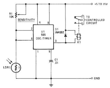
The following circuit illustrates a Photo Alarm Electronic Circuit. This circuit is based on the 555 Timer IC and incorporates features such as an LDR (light-dependent resistor). The Photo Alarm Electronic Circuit utilizes a 555 Timer IC configured in monostable...
This page outlines how to create a simple theft deterrent that can be quite effective. The concept involves using a flashing red LED to indicate that the vehicle is protected. This device serves to safeguard the car from potential...
This circuit converts a positive voltage to a negative voltage, resulting in a loss of approximately 1.5 V. For instance, supplying 9 V to the circuit yields an output of -7.5 V. Additionally, this circuit can function as a...
A laser trip wire that activates a camera. An ambient light sensor from Vishay, the TEMT6000, operates as an NPN transistor connected to a 555 timer in bistable mode. The output is directed to a logic inverter for quick...
The control terminal at 5 feet and the threshold end at 6 feet represent two internal input voltage comparators. As long as the voltage at 6 feet exceeds the voltage at 5 feet by 5 mV, the 555 timer...