
Photo Alarm ElectronicCircuit With 555 Timer IC
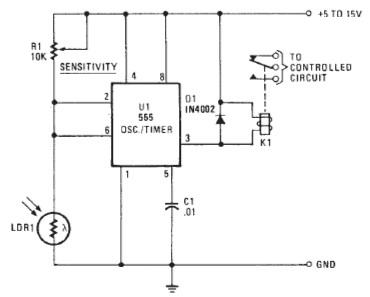
The Photo Alarm Electronic Circuit utilizes a 555 Timer IC configured in monostable mode to create an alarm system that activates in response to changes in light levels. The circuit primarily consists of an LDR, which serves as the light sensor, and a resistor that forms a voltage divider with the LDR. The output from this voltage divider is fed into the trigger pin of the 555 Timer.
When ambient light levels drop below a certain threshold, the resistance of the LDR increases, causing the voltage at the trigger pin to fall below 1/3 of the supply voltage. This triggers the 555 Timer, activating the output pin, which can drive a relay or an alarm system. The duration for which the alarm remains active is determined by the timing components (resistors and capacitors) connected to the 555 Timer, allowing for customization of the alarm duration.
To ensure proper operation, it is crucial to select an appropriate LDR and timing components based on the specific application requirements. The circuit can be powered using a standard DC power supply, and additional features such as a reset button or adjustable sensitivity can be incorporated to enhance functionality. This design is suitable for various applications, including security systems, automated lighting, and other light-sensitive control systems.he following circuit shows a Photo Alarm Electronic Circuit. This circuit based on the 555 Timer IC. Features: LDR ( photoresistive cell), .. 🔗 External reference
Related Circuits

The circuit is primarily composed of the integrated voice chip ISD2560. The Winbond ISD2560 is a chip with robust voice recording capabilities, featuring a permanent memory circuit for voice recording. It has a recording duration of 60 seconds and...
This is a complete alarm system with 5 independent zones suitable for a small office or home environment. It uses just 3 CMOS ICs and features a timed entry/exit zone, 4 immediate zones, and a panic button. There are...

This post discusses a proximity detector circuit primarily utilizing the NE555 integrated circuit (IC). The circuit is designed for burglar alarms based on beam interruption, with the advantage that the transmitter and receiver are contained within the same enclosure,...
The purpose of this circuit is to power a lamp or other apparatus for a specified duration (30 minutes in this case) and then turn it off. It is particularly useful for reading in bed at night, as it...
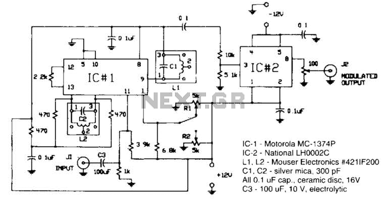
Circuit for applying a DC-coupled FM or PPM to a 555 configured as an oscillator. IC-1 is a Motorola MC-1374P, and IC-2 is a National LH0002C. L1 and L2 are Mouser Electronics #421IF200. C1 and C2 are silver mica...

The voltage rating of the 470 µF capacitor is not critical, provided it significantly exceeds the maximum power supply voltage, which is 12 volts in this circuit. It is essential to connect this capacitor correctly, observing its polarity. The...
Warning: include(partials/cookie-banner.php): Failed to open stream: Permission denied in /var/www/html/nextgr/view-circuit.php on line 713
Warning: include(): Failed opening 'partials/cookie-banner.php' for inclusion (include_path='.:/usr/share/php') in /var/www/html/nextgr/view-circuit.php on line 713