
555 Applications and Examples

The 555 timer IC is a versatile and widely used component in electronic circuits, known for its ability to function in various modes such as astable, monostable, and bistable configurations. In astable mode, the 555 can generate a continuous square wave output, making it suitable for applications such as clock pulses, LED flashers, and tone generation. The frequency and duty cycle of the output can be adjusted by changing the resistor and capacitor values in the circuit.
In monostable mode, the 555 timer acts as a one-shot pulse generator. When triggered, it produces a single output pulse of a specified duration, which can be used in applications like timers, pulse width modulation, and delay circuits. The length of the output pulse is determined by the resistor and capacitor connected to the timing pins of the 555.
Bistable mode allows the 555 to act as a flip-flop, providing a stable output that can be toggled between two states. This configuration is often used in memory storage applications, switch debouncing, and simple control systems.
The schematics included in this collection likely illustrate these various modes of operation, showcasing how the 555 timer can be integrated into different circuits. Each schematic can serve as a valuable reference for understanding the practical applications of the 555 timer, facilitating the design and implementation of electronic projects. Proper analysis of the circuit components, their values, and connections will provide insights into the functioning and versatility of the 555 timer in real-world applications.A collection of drawings of different 555 applications. Some are drawings of schematics found on the web and in books, and saved for my own reference. I did not save the web pages that these originated from, so some may not have proper attribution. If you will point it out, I will be more than happy to oblige. My thanks to you all. 🔗 External reference
Related Circuits
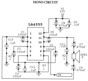
The following circuit illustrates an audio amplifier mono circuit diagram. This circuit is based on the LA4555 integrated circuit (IC). Features include a mono configuration and a power output of 2.3 watts. The audio amplifier circuit utilizing the LA4555 IC...
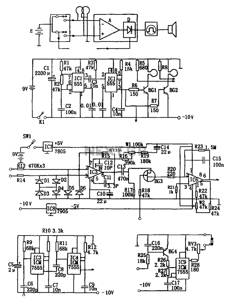
The figure illustrates a double coil metal detector circuit, which consists of a probe, a transmitter, a receiver, a timer, sound transmitters, and other components. The transmitter circuit, depicted in (b), is composed of a multivibrator (IC1, R1, R2,...
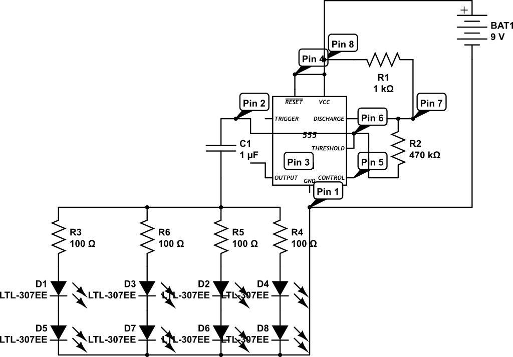
LEDs are rated for a continuous current of only 30 mA, while this circuit operates them at approximately 50 mA. Although this is acceptable for low duty cycles with short pulses, the intended design has a high duty cycle....

This circuit sets the time using a simple model that can accurately maintain the time over extended periods. It employs the CA3140 integrated circuit for its functionality. The circuit utilizes the CA3140 operational amplifier, which is known for its high...

The circuit described here counts the number of times an infrared beam is interrupted. It can be utilized to count the number of individuals entering a room or to track how often an object, such as a ball, passes...
The following circuit illustrates the use of a 555 integrated circuit (IC) for an infrared (IR) remote control extender circuit. Features include support for 850 nm and 950 nm signal wavelengths, along with the capability to generate control pulses. The...