
Simple Timer by CA3140 + NE555
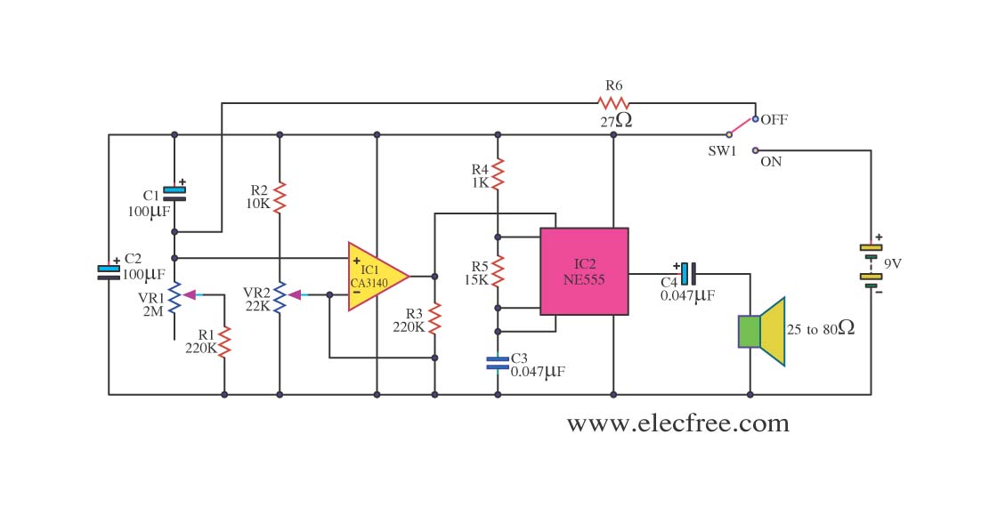
The circuit utilizes the CA3140 operational amplifier, which is known for its high precision and stability, making it suitable for timekeeping applications. The design typically includes a timing capacitor and resistor network that determines the time interval. The CA3140 is configured in an astable multivibrator or as part of a more complex timing circuit, depending on the desired accuracy and time range.
The timing capacitor, when charged and discharged through the resistor network, creates a square wave output that can be used to drive a digital display or trigger other timing-related functions. The choice of capacitor and resistor values is crucial, as they directly influence the frequency of oscillation and, consequently, the timing accuracy.
Additional components may include diodes for reverse polarity protection and transistors for driving higher loads. The circuit can be powered by a stable DC voltage source, ensuring that the timing remains consistent over time. By using high-quality components and careful layout techniques, the circuit can achieve long-term stability and reliability, making it suitable for various applications, including clocks, timers, and event counters.This be the circuit sets the time to model is simple,at can fix the time had long ago and have tall good accuracy. By use pillar equipment be IC CA3140 for.. 🔗 External reference
Related Circuits

This is a simple servo tester designed to thoroughly evaluate the capabilities of nearly any modern servo. It features two pushbuttons, labeled CENTRE and SWEEP, along with a potentiometer that functions in the following manner: The servo tester circuit is...
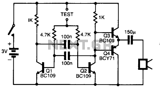
The pitch of the tone is dependent upon the resistance under test. The tester will respond to resistance of hundreds of kilohms, yet it is possible to distinguish differences of just a few tens of ohms in low-resistance circuits....
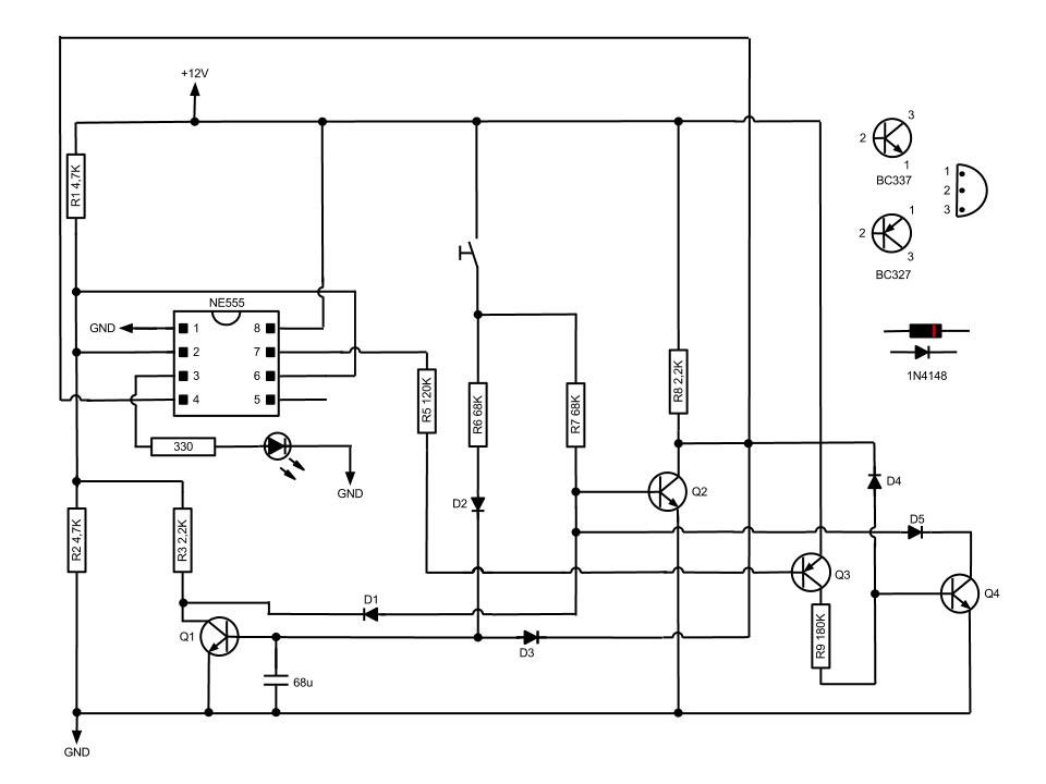
This circuit, based on the NE555 timer IC, toggles the output on and off using a momentary switch. It functions similarly to a mechanical latching relay but resets to its initial state when the power supply is turned off....
This timer circuit is similar to the 5 to 30 minute timer, but when switch S1 is closed, the on/off action of the circuit continues indefinitely until S1 is opened again. A 7555 timer and a low leakage capacitor...
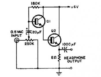
This schematic diagram illustrates a simple headphone amplifier circuit constructed using two NPN transistors. Suitable transistor options include the BC549C, as well as other NPN transistors such as the European equivalents BC548C, BC547C, BC239, 2N5818, or 2N2222. An audio...
this is a very easy circuit to build - all parts can be found at the local electronics shop. The described circuit is characterized by its simplicity and accessibility, making it an ideal project for beginners or those looking to...