
Audio Amplifier MonoCircuit With LA4555 IC

The audio amplifier circuit utilizing the LA4555 IC is designed for mono sound applications, making it suitable for various audio amplification needs. The LA4555 is a power amplifier IC that provides high efficiency and low distortion, making it ideal for driving small speakers in portable devices or low-power audio systems.
In this circuit, the LA4555 is typically configured with external components such as resistors, capacitors, and possibly a heat sink to enhance thermal performance. The input signal is fed into the amplifier through a coupling capacitor that blocks DC voltage, ensuring that only the AC audio signal is amplified. The gain of the amplifier can be adjusted by selecting appropriate resistor values in the feedback loop.
The output stage of the LA4555 delivers up to 2.3 watts of power, which is sufficient for driving small speakers or headphones. The circuit may include additional features such as power supply decoupling capacitors to stabilize the voltage and prevent noise from affecting the audio quality.
Overall, this mono audio amplifier circuit is a practical solution for applications requiring compact and efficient audio amplification, such as in portable audio devices, television sets, and small home audio systems.The following circuit shows about Audio Amplifier Mono Circuit Diagram. This circuit based on the LA4555 IC. Features: mono circuit, 2.3 watts .. 🔗 External reference
Related Circuits
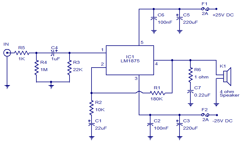
This weblog focuses on electronic circuit schematics, PCB design, DIY kits, and electronic project diagrams. The featured project is a 20W audio amplifier circuit based on the LM1875 audio amplifier IC from National Semiconductors. With a 25V power supply,...
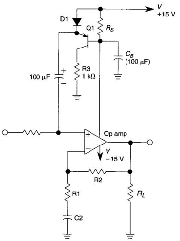
This circuit is an Automatic Gain Control (AGC) system designed for audio-frequency signals. AGC systems typically consist of three main components: an amplifier, a rectifier, and a controlled impedance. In this particular circuit, the functions of both the amplifier...
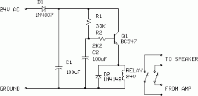
This is a minimal circuit designed for individual audio amplifier projects to control the presenter output relay. The purpose of this circuit is to manage the relay that activates the speaker output within the audio amplifier. The circuit introduces...
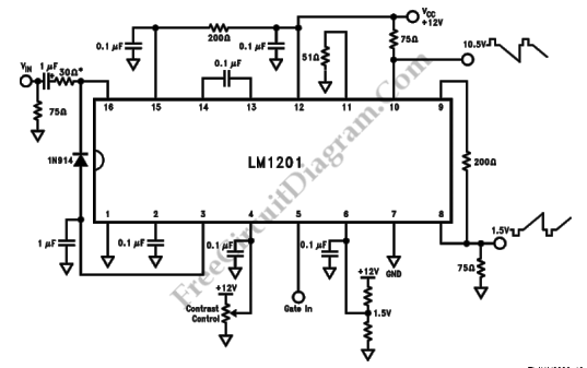
This is a schematic diagram of a video amplifier circuit with bi-phase output. The bi-phase output generates both positive-going and negative-going signals, enabling balanced signaling. The primary component of this circuit is the LM1201. In this configuration, the inverted...
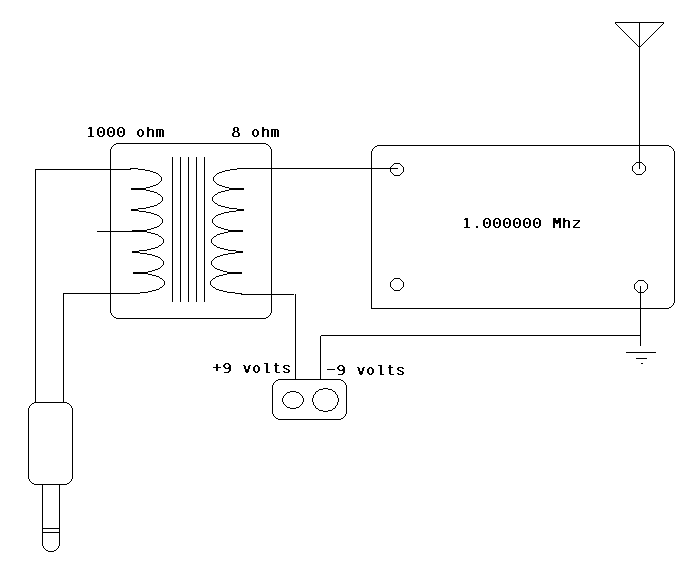
The circuit incorporates an audio transformer. There is an ongoing effort to understand the concept of impedance and its significance. Clarification is sought on the necessity of an audio transformer and its function in changing impedance. An inquiry is...
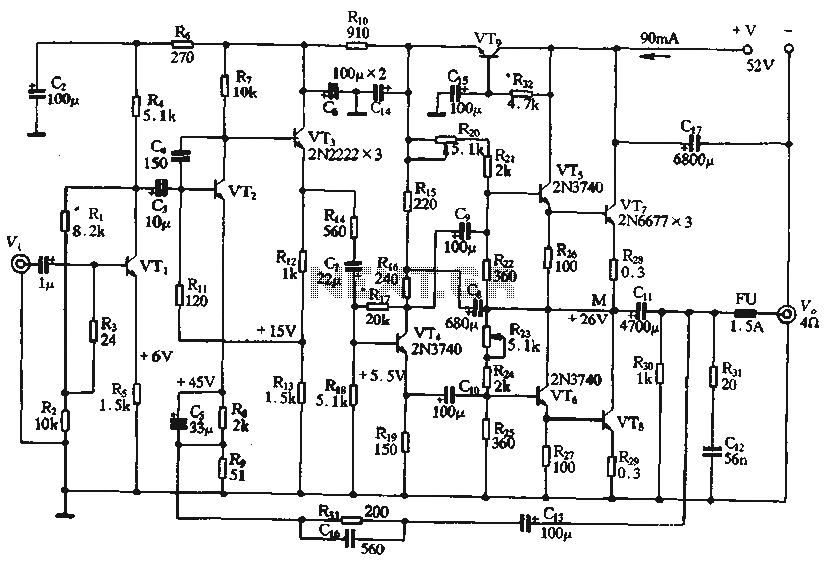
The circuit depicted in the figure is a highly technical OTL (Output Transformer-Less) amplifier circuit. It features a frequency response range of 10 Hz to 100 kHz and exhibits a total harmonic distortion of less than 0.1%, which is...