
555 as the core of a circuit diagram of proximity switch

The circuit utilizes the 555 timer IC, a versatile and widely used component in various electronic applications. In the monostable configuration, the 555 timer generates a single output pulse of a specified duration in response to an external trigger. The duration of the pulse is determined by the resistor (R1) and capacitor (C1) values, following the formula T = 1.1 * R1 * C1, where T is the pulse width.
In this design, R2 serves to pull the trigger pin (Pin 2) high, ensuring that the circuit remains inactive until a triggering event occurs. The metal plate electrodes act as the sensing mechanism, detecting the presence of a nearby object, such as a hand or body. Upon detection, the electrodes generate a low signal that is fed to Pin 2, causing the 555 timer to switch from its stable state to an active state, producing a high output pulse.
Capacitor C2 plays a crucial role in filtering out any noise or interference that may affect the signal integrity. By smoothing out voltage fluctuations, C2 helps to ensure that the output pulse is clean and reliable. This feature is particularly important in environments where electromagnetic interference may be present.
The output from the 555 timer can be used to control various devices, such as relays, LEDs, or other components, enabling the circuit to function as an activation mechanism for electrical appliances, toys, or alarm systems. This flexibility makes the proximity switch circuit a valuable addition to many electronic projects, providing a simple yet effective means of detecting proximity and triggering actions accordingly. As shown, the proximity switch 555 as the core component monostable trigger circuit. 555 Trigger Pin 2 through the large resistance R2 connected to VDD, is waiting for a trigge r condition. When the body close to or touch the metal plate electrodes, since the sensor signal 555 is triggered, a one-shot pulse output. C2 filtering for interference. The circuit can be used for electrical appliances, toys or alarm circuit.
Related Circuits
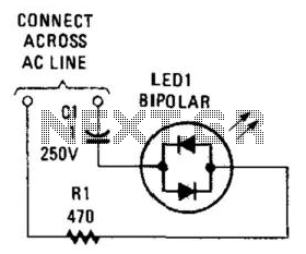
Many electronic circuits require an indication that they are powered. For most AC circuits, a neon lamp is the preferred device. A bidirectional tricolor LED can also be utilized if a capacitor is connected in series with the LED...

The Pyro Propeller Clock POV schematic is relatively straightforward. It consists of three primary components: the power supply utilizing a 7805 voltage regulator, the LED output control managed by a PIC18F252 microcontroller and a 74LS373 latch, and the 'home'...
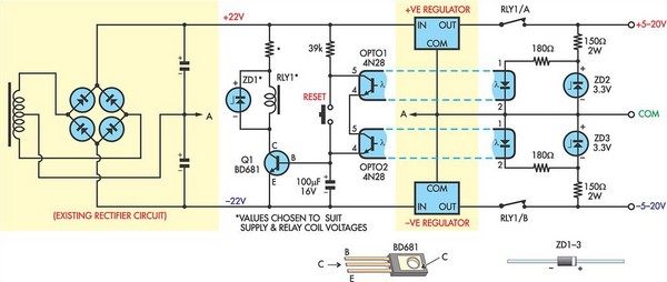
This circuit was designed to protect a dual rail power supply from shorts across the two rails. It uses an optocoupler to monitor each supply rail, with the internal LEDs powered from ZD2 and ZD3 and the associated resistors....
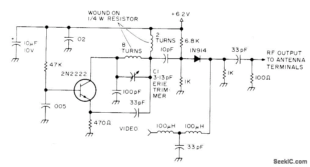
Developed as an interface between the General Instruments AY-3-8500-1 TV game chip and the antenna terminal of a TV set. Adjust capacitor C1 to the frequency of an unused channel to which the receiver is set for playing games....
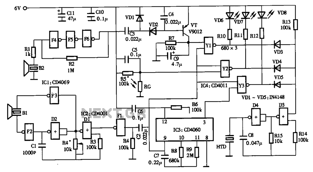
The timing circuit utilizes an electronic switch composed of F1, F2, and VT1 to reduce quiescent current to approximately 1 to 2 A with the 555 timer. Upon initial power-up, the voltage across capacitor C2 cannot instantly change, causing...
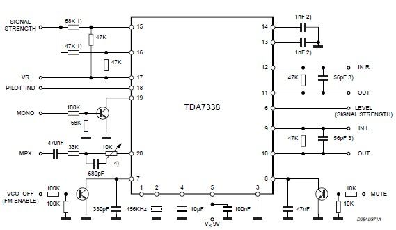
The pilot detector output is configured as an open collector output, necessitating the use of an external pull-up resistor. To set the decoder to "MONO," Pin 19 must be clamped to a voltage lower than 0.8V. The open collector output...