
short circuit protection for balanced
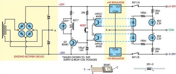
The circuit design incorporates a dual rail power supply protection mechanism utilizing optocouplers for voltage monitoring. The optocouplers are configured such that their internal light-emitting diodes (LEDs) are powered by Zener diodes ZD2 and ZD3, which stabilize the voltage across the LEDs and ensure consistent operation. The associated resistors are selected to limit the current through the LEDs to safe levels, thus preventing damage to the components.
In normal operation, when the supply rails are functioning correctly, the LEDs in the optocouplers illuminate, activating the internal phototransistors. This activation allows current to flow through transistor Q1, which in turn energizes relay RLY1. The energized relay maintains the connection between the power supply rails, allowing the system to operate normally.
In the event of a short circuit across either rail, the corresponding optocoupler's LED will turn off, resulting in the deactivation of its internal phototransistor. This deactivation removes the base current from transistor Q1, causing it to turn off. Consequently, relay RLY1 is de-energized, breaking the connection between the supply rails and protecting the circuit from potential damage due to overcurrent conditions.
To restore operation after a fault condition, a reset button is incorporated into the design. Pressing this button re-enables the circuit, allowing the optocouplers to function normally again, provided that the short circuit has been cleared.
The selection of ZD1 and its associated resistor is critical, as these components must be appropriately rated to handle the supply voltage and the relay coil voltage. This ensures that the circuit operates effectively under different load conditions while providing reliable protection to the power supply system.This circuit was designed to protect a dual rail power supply from shorts across the two rails. It uses an optocoupler to monitor each supply rail, with the internal LEDs powered from ZD2 and ZD3 and the associated resistors. While the LEDs are on, the optocouplers internal transistors are both turned on which ensures that transistor Q1 is on and
relay RLY1 is energised. If either rail is short-circuited, the associated optocoupler is turned off, robbing Q1 of base current and the relay then drops out to disconnect the supply rails. Operation is restored by pressing the reset button. The value of ZD1 and the associated resistor should be chosen to suit the supply and relay coil voltages.
🔗 External reference
Related Circuits
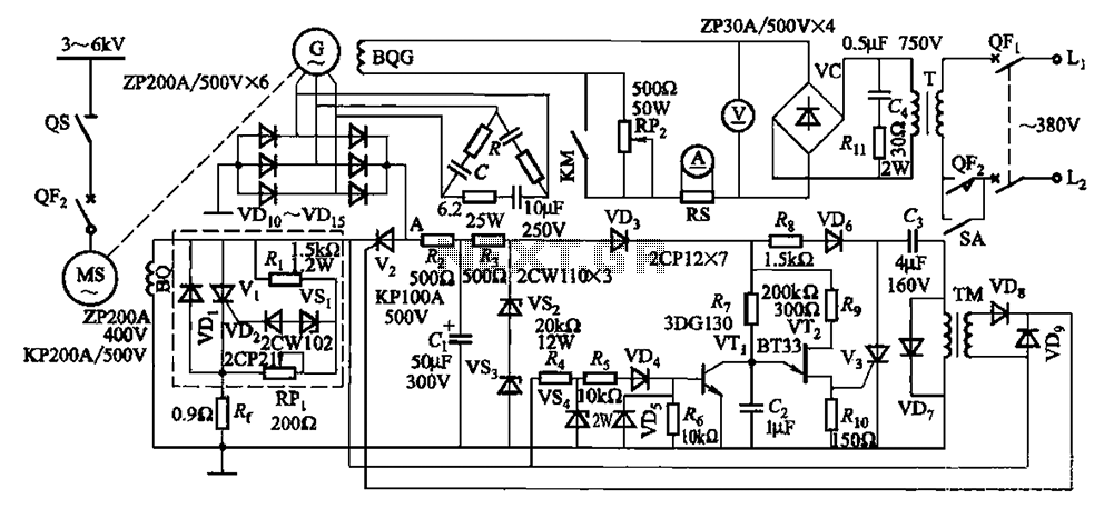
The circuit depicted in Figure 16-105 illustrates a synchronous motor. The components include BQ, which represents its field winding, and G, which denotes the AC excitation for the motor. The notation BQG indicates the field winding, with an empty...
The discharge process in the memory circuit is an instantaneous action, followed by a delay reset circuit. When the input signal is activated, the circuit opens. Once the input signal is removed, the circuit begins counting after a predetermined...
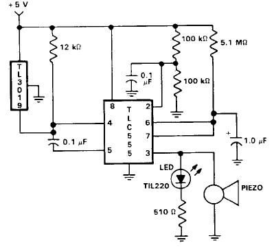
This door open alarm electronic project is designed using a linear hall effect device and a 555 timer circuit. The project utilizes the TL3103 linear hall effect device for detecting the angle of rotation. The TL3103 is positioned within...
In this circuit, an LM339 quad voltage comparator is used to generate a time delay and control a high current output at low voltage. Approximately 5 amps of current can be obtained using a couple of fresh alkaline D...
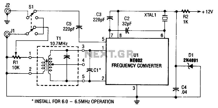
The NE602 (U1) includes oscillator and mixer stages. The mixer merges the oscillator signal with the input RF signal to generate signals whose frequencies are the sum and difference of the input frequencies. For instance, a 7.5-MHz signal received...
The metal detector circuit consists of several key components including the probe oscillator, reference oscillator, oscillation signal processor, mixing amplifier, and ammeter PA. The probe oscillator is made up of the oscillating tube VI, exploration coil L1, capacitors C1...
Warning: include(partials/cookie-banner.php): Failed to open stream: Permission denied in /var/www/html/nextgr/view-circuit.php on line 713
Warning: include(): Failed opening 'partials/cookie-banner.php' for inclusion (include_path='.:/usr/share/php') in /var/www/html/nextgr/view-circuit.php on line 713