
Pyro Propeller Clock POV Circuit

The Pyro Propeller Clock POV (Persistence of Vision) schematic is designed to facilitate a captivating visual display by employing a combination of electronic components that work in unison. The power supply section, based on the LM7805 voltage regulator, ensures a stable +5V output necessary for the operation of the entire circuit. The inclusion of a DC filtering capacitor serves to smooth out any voltage spikes, ensuring the reliability of the power supply under varying load conditions.
The LED output control is a critical aspect of the design, utilizing the PIC18F252 microcontroller, which is programmed to manage the data flow to the LEDs through the 74LS373 latches. The microcontroller's 8-bit data bus allows for efficient communication with the latches, while the two control lines facilitate the selection of which latch is currently active. This method of operation, where only one latch is addressed at a time, is advantageous as it simplifies the control logic and reduces the complexity of the circuit. The result is a nearly simultaneous update of the LED outputs, creating the illusion of a continuous image when the propeller spins.
The 'home' trigger circuit is essential for maintaining the synchronization of the displayed image. The IR emitter diode emits infrared light, which is detected by the phototransistor. When the IR light is interrupted, the phototransistor switches on, creating a transition from high to low voltage at its collector pin. This transition is detected by the PIC18F252, signaling that the propeller has completed a full rotation and returned to the home position. This feedback mechanism is crucial for ensuring the correct timing and alignment of the visual display, enabling the clock to maintain accurate image representation as it spins.
Overall, the Pyro Propeller Clock POV schematic exemplifies a well-thought-out design that integrates power management, data handling, and position sensing to produce a visually striking display. The careful selection of components and their arrangement within the circuit contribute to the effectiveness and reliability of the final product.The Pyro Propeller Clock POV schematic is actually not very difficult. There are three main parts: the power supply which uses a 7805, the LED output control which uses the PIC18F252 and 74LS373 and the `home` trigger circuit which uses an IR emitter and Phototransistor. This standard +5v power regulation circuit makes use of the LM7805 3-pin T2 20 device. A DC filtering capacitor is attached to its output to prevent high frequency spikes from the power supply. The PIC 18F252 uses an 8-bit data bus system with 2 control lines to tell which 74LS373 latch to output data on the bus to turn on/off LEDs.
With this design, we can only send data to one 74LS373 at a time, which just means LED output updates will be nearly simultaneous instead of 100% simultaneous. In order to know when the system should restart displaying the current image on the propeller clock, we need a known reference point called `home`.
An IR emitter diode shines bright into a phototransistor. This turns the transistor `On` connecting the +5v collector pin to the +0v Emitter pin. The PIC 18F252 will see this `falling edge` transition and know right away it`s back at the home location, 360 °. 🔗 External reference
Related Circuits
The development of the entire system necessitated a thorough identification of all processes related to the laser controller. The initial diagram outlines the primary physical components utilized in the CNC laser system. The setup includes a power supply, a...
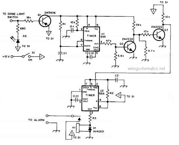
This circuit diagram represents a smart car alarm timer. This design is more advanced compared to traditional car alarm systems. When activated, the alarm remains active for 80 seconds, following an initial delay of 15 seconds. The smart car alarm...
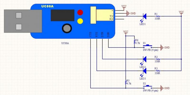
The LEDs operate in an active-low configuration (0), while the initial state of the switches is high (1). In other words, the PC software must send a low signal (0) to activate the LEDs, and if a low signal...
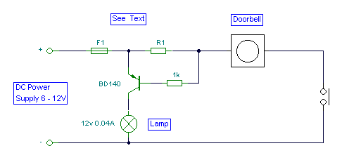
It is easy to miss the sound of a doorbell while watching TV. This circuit addresses the issue by providing a visual indication, such as a lamp or an LED. Connecting a lamp directly in parallel with the doorbell...

ECL integrated circuit non-saturated digital logic circuits. CMOS and ECL interface circuit shown in cross. ECL (Emitter Coupled Logic) integrated circuits are designed to operate in a non-saturated mode, providing high-speed digital logic functionality. These circuits are characterized by their...
The Phase-Locked Loop (PLL) will synchronize with an input signal, providing both triangle and square wave outputs. A quad operational amplifier can be utilized in this circuit, making it suitable for audio and low-frequency radio applications. The Phase-Locked Loop (PLL)...