
555 audio oscillator
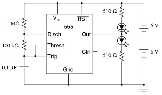
The described circuit involves a 555 timer configured as an astable multivibrator, which is a fundamental application of the IC. The 555 timer operates in an astable mode by continuously switching between its high and low states without requiring external triggering. The timing components, specifically the resistors and capacitor, dictate the frequency of oscillation and the duty cycle of the output waveform.
In this configuration, the two resistors (1 MΩ and 100 kΩ) and the capacitor form an RC timing network that determines how fast the capacitor charges and discharges. The charging time (T_high) can be calculated using the formula:
\[ T_{high} = 0.693 \times (R_1 + R_2) \times C \]
where \( R_1 \) is 1 MΩ, \( R_2 \) is 100 kΩ, and \( C \) is the capacitance in farads. The discharging time (T_low) is given by:
\[ T_{low} = 0.693 \times R_2 \times C \]
The total period (T) of the output waveform is the sum of T_high and T_low:
\[ T = T_{high} + T_{low} \]
The frequency (f) can then be derived from the total period:
\[ f = \frac{1}{T} \]
This relationship indicates that adjusting either the resistor or capacitor values will directly influence the frequency of the output square wave. The duty cycle can also be calculated as:
\[ Duty\ Cycle = \frac{T_{high}}{T} \times 100\% \]
By experimenting with different resistor and capacitor values, one can observe the changes in frequency and duty cycle, which can be visually represented through the brightness of the LEDs. The circuit provides a practical demonstration of the 555 timer's capabilities, illustrating fundamental concepts of timing, waveform generation, and the relationship between charge and discharge in capacitive circuits.A oscilloscope would be useful in analyzing the waveforms produced by this circuit, but it is not essential. An audio detector is a very useful piece of test equipment for this experiment, especially if you don`t have an oscilloscope.
The "555" integrated circuit is a general-purpose timer useful for a variety of functions. In this experiment, we explore its use as an astable multivibrator, or oscillator. Connected to a capacitor and two resistors as shown, it will oscillate freely, driving the LEDs on and off with a square-wave output voltage. This circuit works on the principle of alternately charging and discharging a capacitor. The 555 begins to discharge the capacitor by grounding the Disch terminal when the voltage detected by the Thresh terminal exceeds 2/3 the power supply voltage (Vcc).
It stops discharging the capacitor when the voltage detected by the Trig terminal falls below 1/3 the power supply voltage. Thus, when both Thresh and Trig terminals are connected to the capacitor`s positive terminal, the capacitor voltage will cycle between 1/3 and 2/3 power supply voltage in a "sawtooth" pattern.
During the charging cycle, the capacitor receives charging current through the series combination of the 1 M © and 100 k © resistors. As soon as the Disch terminal on the 555 timer goes to ground potential (a transistor inside the 555 connected between that terminal and ground turns on), the capacitor`s discharging current only has to go through the 100 k © resistor.
The result is an RC time constant that is much longer for charging than for discharging, resulting in a charging time greatly exceeding the discharging time. The 555`s Out terminal produces a square-wave voltage signal that is "high" (nearly Vcc) when the capacitor is charging, and "low" (nearly 0 volts) when the capacitor is discharging.
This alternating high/low voltage signal drives the two LEDs in opposite modes: when one is on, the other will be off. Because the capacitor`s charging and discharging times are unequal, the "high" and "low" times of the output`s square-wave waveform will be unequal as well.
This can be seen in the relative brightness of the two LEDs: one will be much brighter than the other, because it is on for a longer period of time during each cycle. The equality or inequality between "high" and "low" times of a square wave is expressed as that wave`s duty cycle.
A square wave with a 50% duty cycle is perfectly symmetrical: its "high" time is precisely equal to its "low" time. A square wave that is "high" 10% of the time and "low" 90% of the time is said to have a 10% duty cycle.
In this circuit, the output waveform has a "high" time exceeding the "low" time, resulting in a duty cycle greater than 50%. Use the audio detector (or an oscilloscope) to investigate the different voltage waveforms produced by this circuit.
Try different resistor values and/or capacitor values to see what effects they have on output frequency or charge/discharge times. 🔗 External reference
Related Circuits
Pulses are received by the timer from the distributor points. When the timer output is high, Meter M receives a calibrated current through R6. The meter does not... The circuit described involves a timer that receives pulse signals from distributor...
This is a basic 555 square wave oscillator designed to generate a 1 kHz tone for an 8-ohm speaker. In the circuit, the speaker is isolated from the oscillator by an NPN medium power transistor, which supplies more current...
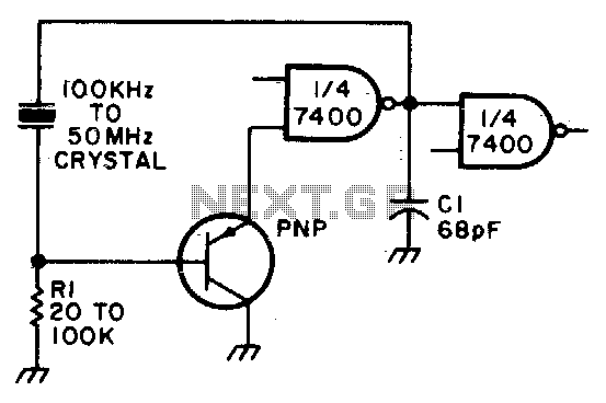
Adjust Rl for approximately 2 volts at the output of the first gate. Additionally, adjust Cl for optimal output. In the context of electronic circuit design, the output voltage of a gate, such as a logic gate or operational amplifier,...
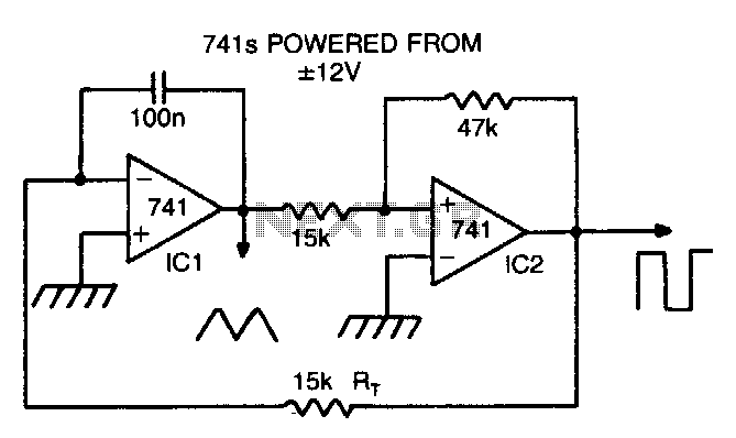
By making Rt variable, it is possible to alter the operating frequency over a 100 to 1 range. The versatile triangle/square wave oscillator has a possible frequency range of 0 Hz to 100 kHz. The described circuit features a variable...
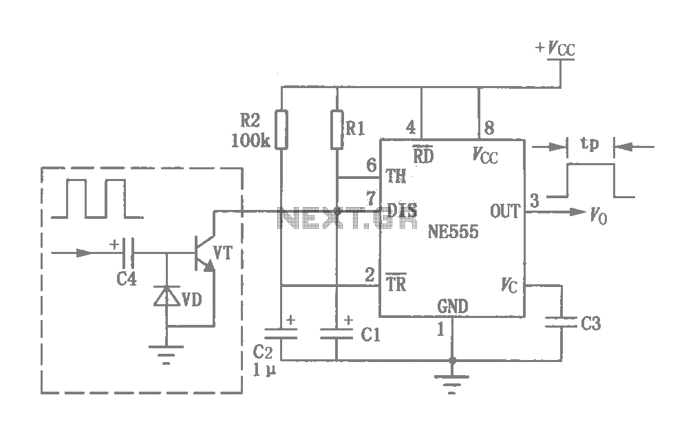
This circuit was originally a type of power-delay control circuit, where the delay time is determined by the timing elements R1 and C1. Additionally, with the inclusion of a "watchdog" circuit, it can be utilized as a monitoring circuit...
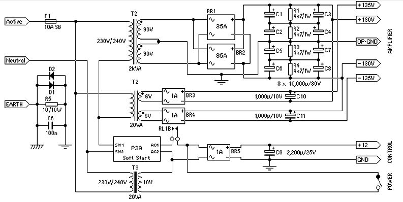
Power supply for a 1500-watt audio power amplifier. This power supply circuit is paired with a high-power audio amplifier rated at 1500 watts. A serious approach is required to design the power supply for the amplifier. First, a step-down...