
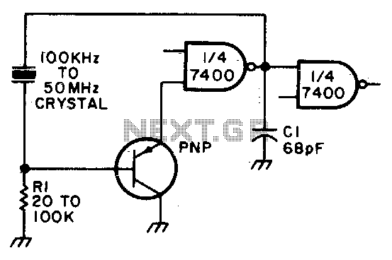
Ttl-compatible crystal oscillator
No description available.
Related Circuits
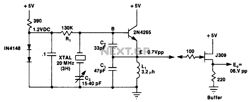
L1 and C1 are selected to resonate at a frequency below the desired crystal harmonic but above the crystal's next lower odd harmonic. Capacitor C2 should have a value between 30-70 pF, independent of the oscillation frequency. There is...

This design circuit is intended for sine wave oscillators, providing both sine and square wave outputs across a frequency range from below 20 Hz to above 20 KHz. The oscillation frequency can be easily adjusted by changing a single...
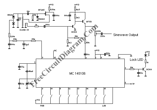
A PLL (Phase-Locked Loop) oscillator is utilized to achieve a very stable frequency with minimal distortion in the sine wave output. Its stability is comparable to that of crystal-based oscillators, while the distortion level of the sine wave output...
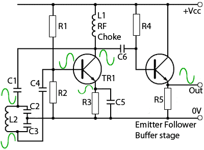
A typical Colpitts oscillator design. This circuit operates similarly to the Hartley oscillator, but the Colpitts LC tank circuit consists of a single inductor and two capacitors. The capacitors effectively form a single tapped capacitor instead of the tapped...
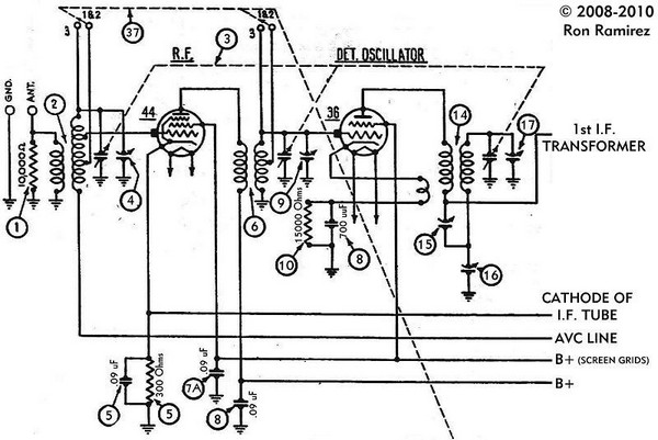
The initial step involves taking notes to indicate which wire connects to each terminal on the 36 tube socket. Remove all wires connected to the 36 tube socket. Next, drill out the rivets that secure the five-pin 36 tube...
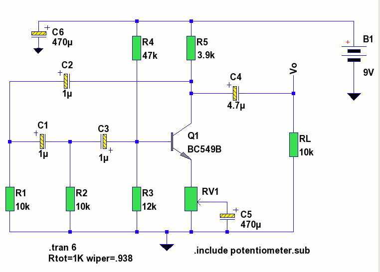
The circuit is a standard RC phase shift oscillator that utilizes a single bipolar transistor as the active component. When power is supplied, regenerative feedback is applied through capacitor C2 from the collector to the base of the transistor....