
555-based solar engine
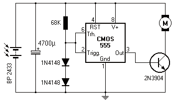
The circuit described is a phototropic device known as a photopopper, which is designed to respond to light in a specific manner. The simplification of the original circuit implies that unnecessary components were removed or optimized to enhance functionality while reducing complexity. A phototropic circuit typically utilizes light-dependent resistors (LDRs) or phototransistors to sense ambient light levels.
In the configuration of the photopopper, it is likely that two or more phototropic sensors are employed to detect light intensity from different angles or sources. This dual approach allows the circuit to react to light changes more effectively, enabling it to perform actions such as activating an output device, which could be a motor or LED, in response to light exposure.
The doubling of the circuit may involve mirroring the original design to create a balanced response to light stimuli, allowing for enhanced sensitivity and faster activation times. The output stage of the circuit might include a transistor or a relay to control a higher power load, ensuring that the photopopper can drive substantial devices while remaining controlled by the low-power phototropic sensors.
Overall, the photopopper design is an innovative approach to creating a responsive electronic system that can react to environmental light changes, with applications ranging from simple educational projects to more complex automated systems in robotics or lighting control.Wilf Rigter simplified this circuit a bit, made it phototropic, and doubled it up to yield a photopopper design in a post later the same day. I`ve got this design written up elsewhere in the library. 🔗 External reference
Related Circuits
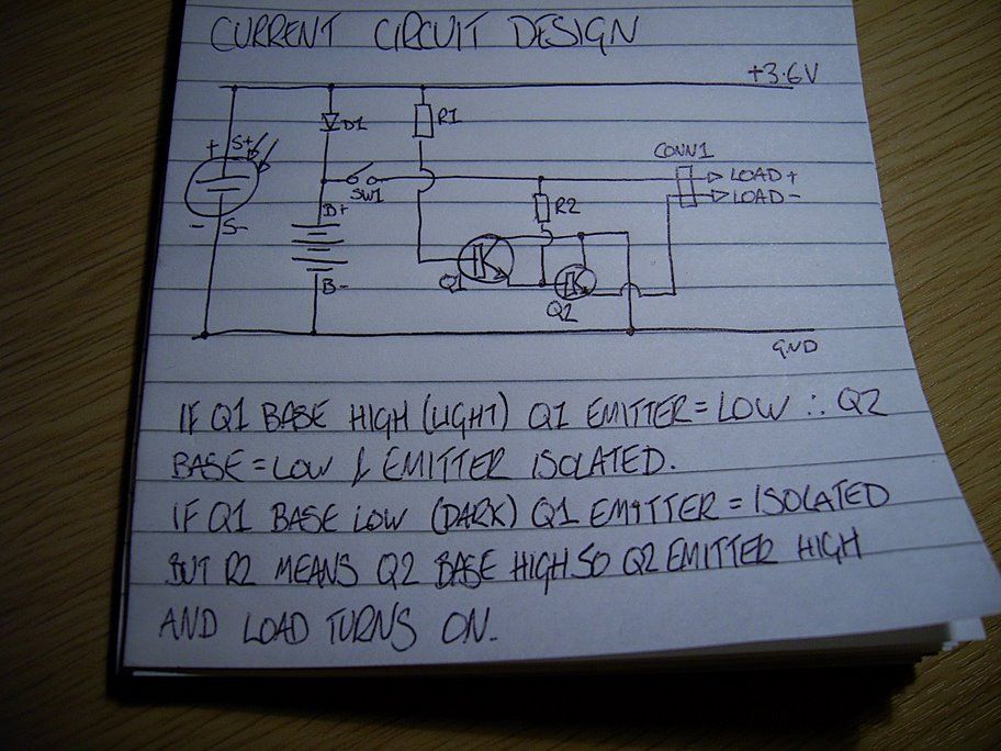
A solar-powered garden light has been purchased, featuring a solar panel that charges batteries. When darkness falls, three LEDs illuminate until either light returns or the batteries deplete. The control box contains three Ni-MH AA batteries with a capacity...
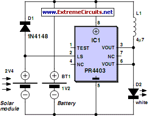
The PR4403 is an advanced version of the PR4402 40mA LED driver. It features an additional input known as LS, which can be activated by pulling it low to illuminate the LED. This functionality simplifies the construction of an...
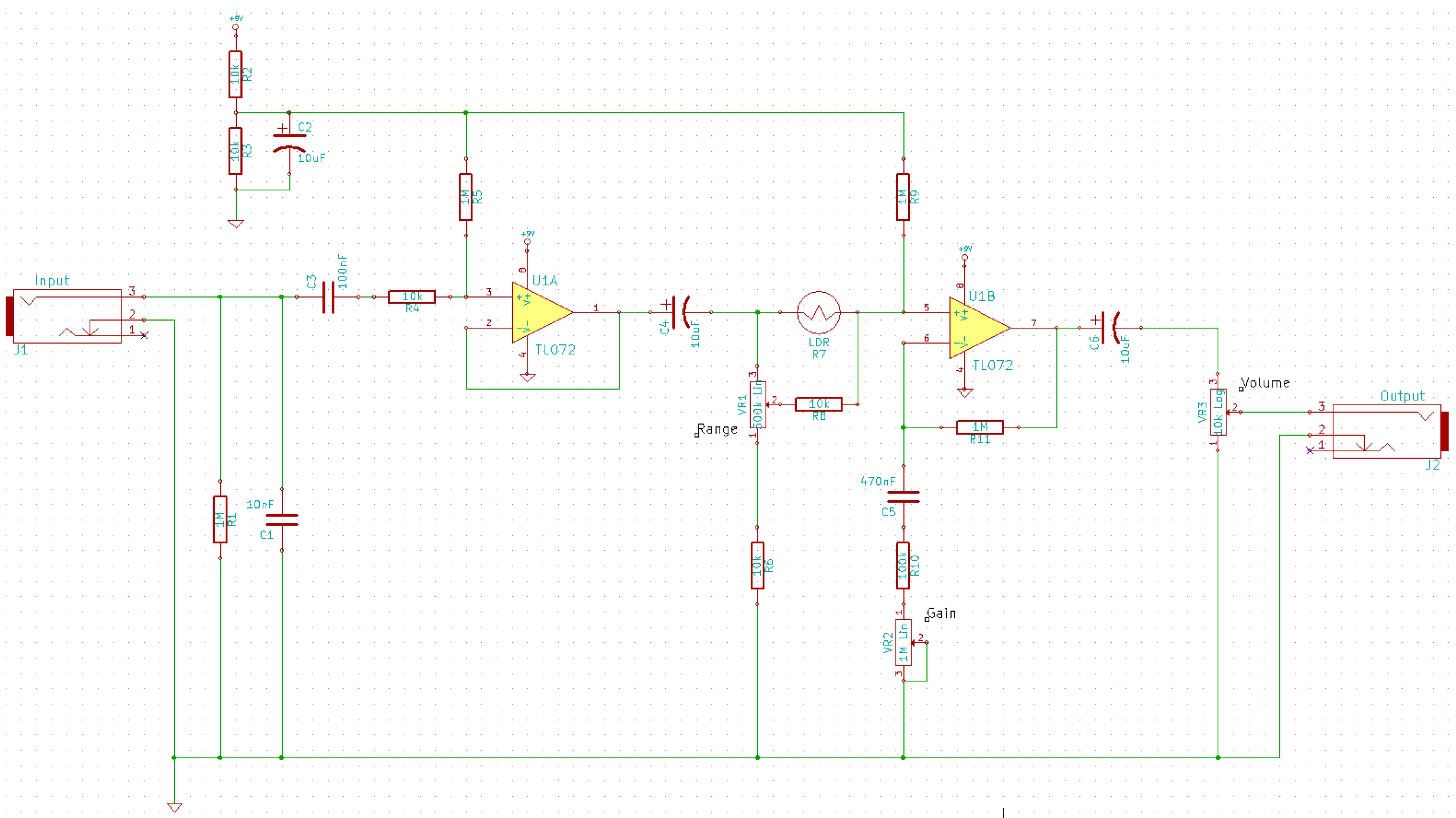
This is a simplified schematic for the Solar Lifeforce. The design eliminates the expression/CV output features and the toggle for the buffer, making it a straightforward circuit. It may benefit from adding small capacitors between R5 and ground, as...
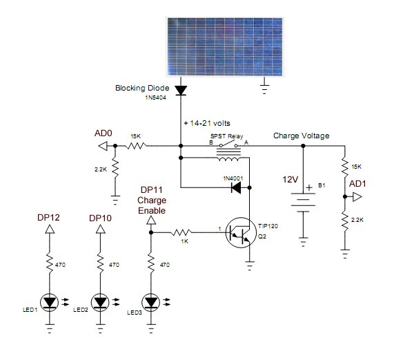
Construction and programming of a PICAXE solar panel battery charge controller. The PICAXE solar panel battery charge controller is designed to manage the charging process of batteries using solar energy. This system typically involves several key components: the solar panel,...
An article detailing the construction of a small solar panel from scratch. The process of building a small solar panel from scratch involves several key components and steps that are crucial for achieving an efficient and functional solar energy system....
Purchase a 1W white LED and utilize a mobile phone battery to create a small lamp. A lampshade can be made from a glass-like milky white plastic bottle. The LED emits light through a radiating plate, which has two...
Warning: include(partials/cookie-banner.php): Failed to open stream: Permission denied in /var/www/html/nextgr/view-circuit.php on line 713
Warning: include(): Failed opening 'partials/cookie-banner.php' for inclusion (include_path='.:/usr/share/php') in /var/www/html/nextgr/view-circuit.php on line 713