
Sonic Kaleidoscope Circuit
The circuit described is a multi-stage audio processing system that begins with a microphone input. The use of an inverting amplifier (U2-a) allows for adjustable gain, which is critical for accommodating various microphone sensitivities and input levels. The subsequent band-pass filters (U2-b, U2-c, U2-d) serve to isolate specific frequency ranges, enabling targeted audio processing for applications such as audio analysis or signal conditioning. The tuning of these filters to specific frequencies (100 Hz, 1000 Hz, and 1500 Hz) suggests a design tailored for audio signals, possibly for audio visualization or frequency response testing.
The coupling between the output of U2-b and the input of U3 through C11 ensures that only the desired AC signal is passed, while DC offsets are blocked, which is essential for accurate signal representation. The use of a load resistor (R15) is also a crucial design feature, ensuring that the subsequent stage (U3) operates correctly by maintaining a defined load, preventing floating outputs that could lead to erratic behavior in the absence of an input signal.
The output stage, which drives LED indicators, provides a visual representation of the processed audio signal. The choice of using series-connected LEDs allows for a clear visual output that can reflect the amplitude of the input signal. The brightness control through resistors (R18, R19, R20) is a thoughtful inclusion, recognizing that different LED colors have different luminous efficiencies and ensuring uniform visibility across the LED spectrum.
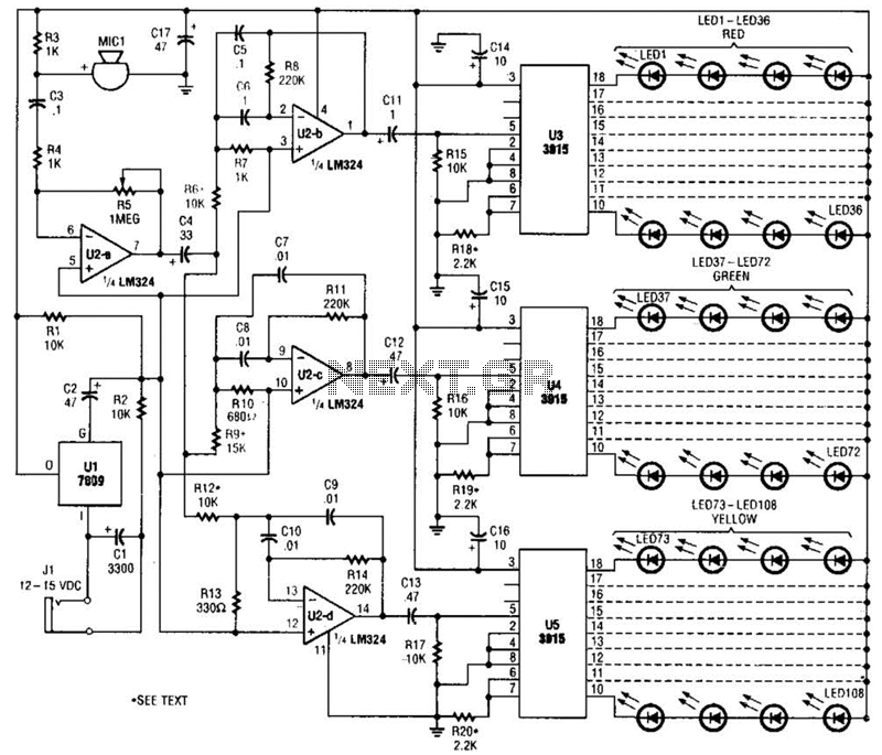
Power management is addressed through the use of a regulated power supply, which is vital for maintaining consistent performance and avoiding fluctuations that can arise from power line noise. The decision to omit an on/off switch reflects a design philosophy focused on simplicity and reliability, emphasizing that the device should be powered down by disconnecting it from the wall pack when not in use. Overall, this circuit design presents a robust solution for audio signal processing with effective visual feedback, suitable for various applications in audio electronics. The microphone input, MIC1, is fed through C3 and R4 to inverting amplifier U2-a; the gain of U2-a is controlled by potentiometer R5. The output of U2-a is fed through C4 to the remaining op-amps (U2-b, U2-c, U2-d), which are all configured as band-pass.filters.
Each filter is tuned to pass a different range of frequencies by its resistor/capacitor combination. With the values shown, U2-b, U2-c, and U2-d have center frequencies of roughly 100, 1000 and 1500 Hz, respectively. Resistors R6, R9, R12 control the bandwidth and gain of their respective filter circuits, and can range in value from 10 to 15 kO.
The output of U2-b is capacitively coupled via Cl 1 to the input of U3, with R15 serving as the load resistor for U2-b. That resistor also keeps U3`s outputs from floating in the absence of a signal. Connected as shown, U3 uses its own internal voltage reference to make a full-scale display of 1.2 V. Each of the nine outputs of Uo (output 1 is not used) sinks four, series-connected (red) LEDs. Op amps U2-c and U2-d are similarly connected to U4 and U5, respectively, driving green and yellow LED strings.
Resistors R18, R19, and R20 control the brightness of their corresponding LED arrays, and they must be adjusted accordingly; different, colors of LEDs usually vary in brightness. A lower value of resistance will make the LEDs glow brighter. Power for the circuit is supplied by a 500 mA, 12-15-Vdc wall-pack transformer, via Jl. The output of the transformer is filtered by 01 and is regulated by Ul; regulation is necessary to keep power-line ripple from affecting the display.
The supply pins of U2 through U5 are bypassed by capacitors 014 through 017 to further ensure stability. An on/off switch was deemed unnecessary because the power supply should be unplugged when the unit is not in use.
🔗 External reference
Related Circuits
This circuit gives a low-level output when sufficient lighting is present, functioning as a light detector. It can issue a command to turn on lights when darkness falls. Its output is compatible with TTL levels, providing a low logic...
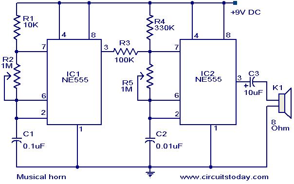
This document outlines a straightforward circuit diagram for a musical horn utilizing two NE555 integrated circuits (ICs). Both ICs are configured as astable multivibrators. The output from the first multivibrator is connected to the discharge pin (pin 7) of...
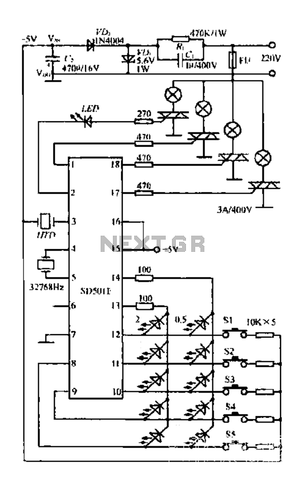
The FIG SD501E is a J tie fan integrated circuit (IC) characterized by progressive timing and three operational modes: strong, medium, and weak. It features three types of output settings and includes an electrical swing mechanism. The device is...
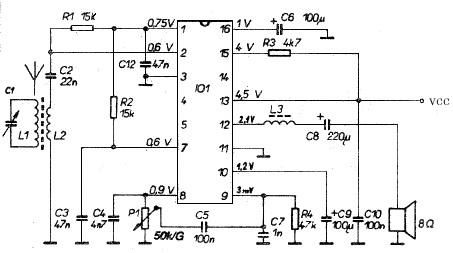
This AM radio receiver circuit utilizes the TDA1083 radio IC, which is suitable for constructing a simple medium frequency (MF) band radio. The schematic operates within a frequency range of 300 kHz to 3 MHz. The circuit is straightforward...
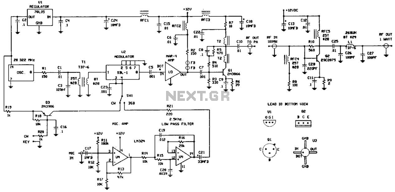
This circuit was detailed in a recent edition of an amateur radio magazine. It enables operation in the 160 to 190 kHz band with a maximum power output of 1 W (license-free) in various modes such as CW, SSB,...
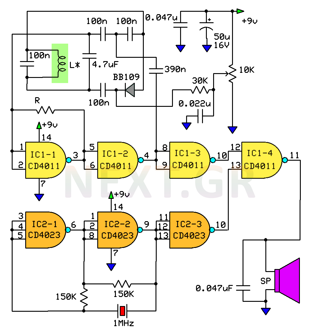
This circuit is a metal detector designed to detect large metallic objects at depths ranging from 2 to 3 meters, depending on the size of the object and the type of soil. The construction is straightforward, making it accessible...
Warning: include(partials/cookie-banner.php): Failed to open stream: Permission denied in /var/www/html/nextgr/view-circuit.php on line 713
Warning: include(): Failed opening 'partials/cookie-banner.php' for inclusion (include_path='.:/usr/share/php') in /var/www/html/nextgr/view-circuit.php on line 713