
555 Christmas Lights Project
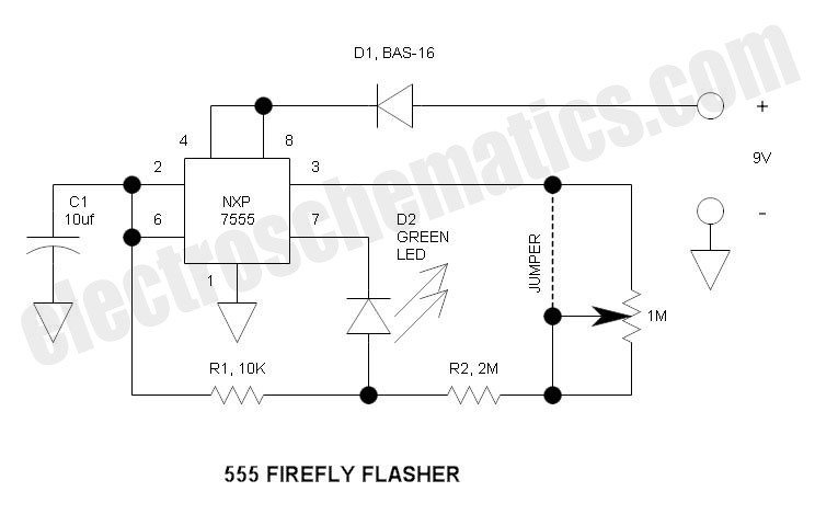
The circuit operates based on the 555 timer's functionality, configured in astable mode for continuous oscillation. The LED's placement in the reset line (pin 7) is a unique approach that provides a dual function: it prevents excessive current draw from the battery while ensuring that the capacitor can discharge adequately. The use of pin 3 as a charge source facilitates a smoother transition during the reset phase, allowing the capacitor to maintain a voltage level conducive to reliable operation.
The reverse polarity diode is a critical safety feature, safeguarding the circuit against damage from incorrect battery installation. The design encourages modularity, enabling the assembly of multiple sections into a single unit, thus providing flexibility in application. The choice of capacitors and their arrangement directly impacts the brightness and performance of the LEDs, making it essential to select components based on the desired outcome.
The project serves as an educational tool, allowing participants to gain hands-on experience with SMD technology and circuit assembly. The emphasis on using commonly available components, such as 0805-sized SMDs, ensures that the project remains accessible to a wide audience. Overall, this circuit design exemplifies innovative thinking in optimizing the use of standard electronic components while providing a platform for learning and experimentation.This is different than the standard 555 oscillator circuit in that the LED is placed in the capacitor reset line (pin 7). By doing so, overall current is reduced and the high peak LED current does not flow out of the battery.
Since the forward drop of the LED can interfere with the reset threshold voltage when the battery voltage is low, the capac itor charge source is via pin 3, the output. In this way, while the capacitor is rapidly resetting via pin 7, it is also being slowly discharged via pin 3 that follows pin 7. That way if the capacitor voltage has a difficult time discharging to the reset voltage (3V or lower), it has a little help via the charge source.
Total current drain is in the order of 500uA. A 9V battery can power this for months. 12V is brighter but less convenient because small 12V batteries are uncommon. Each section can stand alone and has an individual reverse polarity diode. You may think that this diode may be eliminated, but destruction is instant if the battery is accidentally connected reverse. This can be assembled either in a strip of (4) or (6) flashers ” all (6) sections are bussed together.
Three expresspcb. com miniboards yield a total of 18 (4) position, or 12 (6) position flashers. My prototype has (4) different LED colors, but the BOM lists (6) LED colors. Perhaps you can locate other colors you like better. I actually purchased my LEDs on eBay ”they have some good deals. C1 is 10uF for bright LEDs such as White, Blue and Green ”to help equalize brightness for dimmer LEDs, I simply piggybacked (2) 10uF capacitors to get 20uF. As a group project, students can learn how to identify, handle and solder small SMD devices, and test.
The smallest device is the common 0805 size and even I (at my age) can handle this stuff. Smaller sizes such as 0603 or 0402 is electronic dust in my opinion and do not lend itself to hand assembly. The finished piece is an interesting curio that will not get discarded. Purchasing all components for a group gets the volume up and price is significantly reduced. For unto you is born this day in the city of David a Saviour, which is Christ the Lord. And this shall be a sign unto you; Ye shall find the babe wrapped in swaddling clothes, lying in a manger.
And suddenly there was with the angel a multitude of the heavenly host praising God, and saying, Glory to God in the highest, and on earth peace, good will toward men. Luke 2. 11-14 (KJV) 🔗 External reference
Related Circuits
The overhaul includes features such as online judge diodes, the ability to test whether transistors are functioning properly, and the capability to assess TTL logic levels or high impedance states. It can output signals at 37 MHz, bar television...

This Hi-Fi stereo preamplifier circuit is constructed using the TDA1054 integrated circuit (IC) from SGS. The TDA1054 is housed in a 16-pin DIL package and incorporates two separate preamplifier circuits. It is characterized by low noise and minimal issues...
The 555 integrated circuit is a versatile timer that can be used for various applications. This experiment focuses on its operation as an astable multivibrator or oscillator. When connected to a capacitor and two resistors, it generates a square-wave...

The circuit described on this page is designed around Kingbright's 52mm LED cluster module which comprises 50 red LEDs in a waterproof housing with a brightness in excess of 16000mcd. In the original version of this project each LED...
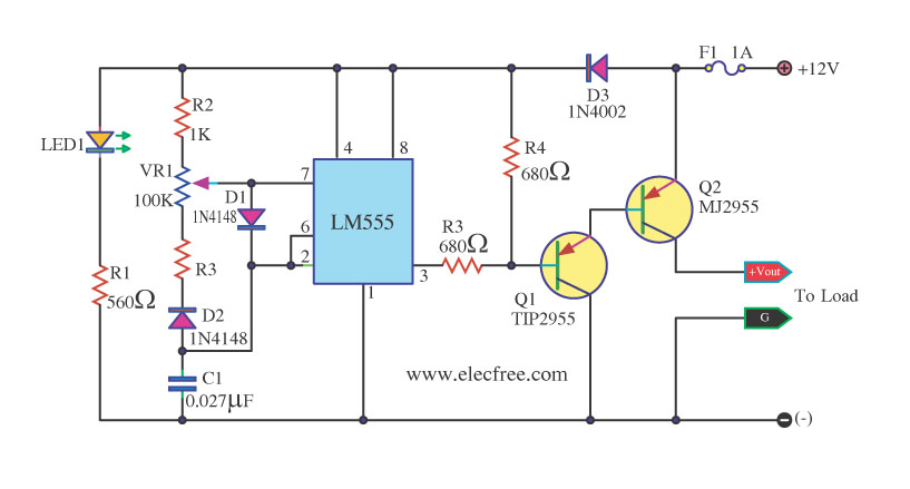
This circuit is a DC dimmer circuit that utilizes the LM555 integrated circuit configured as an astable multivibrator. It is capable of adjusting the duty cycle by fine-tuning variable resistors VR1 and VR2. The DC dimmer circuit employs the LM555...
As a cyclist, there is a constant search for methods to enhance visibility during nighttime rides. The concept of the `NITE-RIDER` was developed to create a distinctive and attention-grabbing rear light for bicycles. This design features nine extra-bright LEDs...
Warning: include(partials/cookie-banner.php): Failed to open stream: Permission denied in /var/www/html/nextgr/view-circuit.php on line 713
Warning: include(): Failed opening 'partials/cookie-banner.php' for inclusion (include_path='.:/usr/share/php') in /var/www/html/nextgr/view-circuit.php on line 713