
Spot lamp dimmer by LM555 and TIP2955
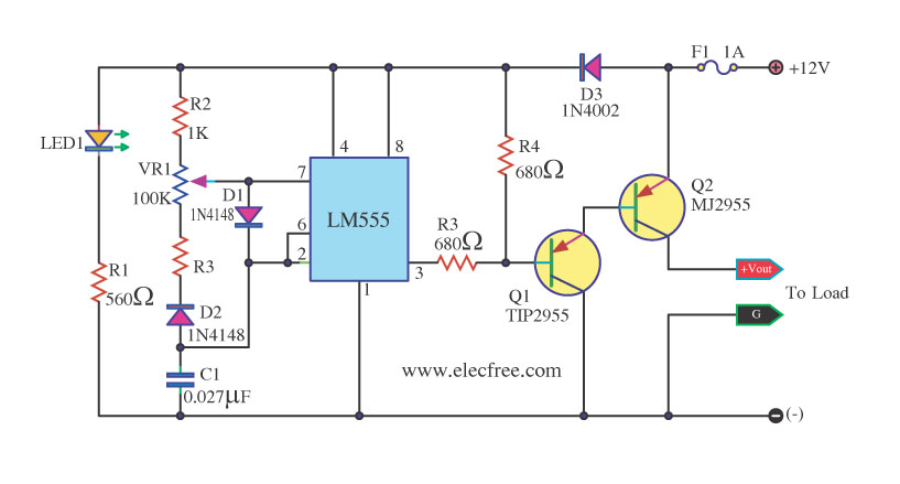
The DC dimmer circuit employs the LM555 timer IC, which is a versatile component widely used in various electronic applications. In this configuration, the LM555 operates in astable mode, generating a continuous square wave output. The frequency and duty cycle of this waveform can be modified by adjusting the values of the resistors VR1 and VR2, which are connected to the timing capacitor.
The operation of the circuit is based on the charging and discharging cycles of the capacitor connected to the LM555. As the capacitor charges through VR1 and discharges through VR2, the time periods for both processes determine the duty cycle of the output signal. A higher resistance in VR1 will increase the charging time, resulting in a longer "on" time for the output signal, thereby dimming the connected load. Conversely, adjusting VR2 will influence the discharging time, further fine-tuning the dimming effect.
This circuit can be applied to control the brightness of DC loads such as LED lights, allowing for energy-efficient operation and user-customizable lighting levels. To ensure stability and performance, it is important to select appropriate values for the timing components, considering the specifications of the load being controlled. Additionally, the circuit may include protection elements like diodes to prevent back EMF from inductive loads, ensuring the longevity of the LM555 and other components used in the circuit.This circuit is DC Dimmer Circuit. By use IC LM555 be model Astable Multi vibrator. It is can change translate Duty Cycle with fining VR1 and VR2 be.. 🔗 External reference
Related Circuits
This is a dual-color lamp designed to illuminate the codes printed on transistors and integrated circuits (ICs). The codes and numbers on the black bodies of these components can be challenging to read in low light conditions due to...
Create LED lighting powered directly from the AC mains (120-Volt AC) due to the unavailability of inexpensive and safe enclosures for the circuitry. While collecting old failed CFLs for recycling, it was noted that the body of CFLs (also...
This circuit is a 73 MHz halogen lamp radio-controlled system. Its purpose is to control the power state of a halogen lamp using a remote control. When the push button on the remote control is pressed, the power state...

Ideal for operating 3 to 24V DC existing on-circuit lamps. This circuit was designed to provide continuous light for lamps already wired into a circuit. The circuit is intended to facilitate the operation of existing DC lamps that are integrated...
The Zener diode may not be providing sufficient current in its breakdown state to activate the transistor. Removing resistor R2 did not resolve the issue. The Zener's voltage selection could be too high, potentially preventing it from regulating the...
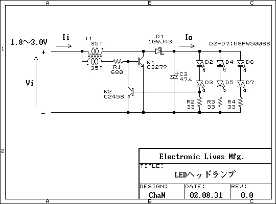
This is a practical white LED head mount lamp (flashlight). Recently many white LED flashlights appear on the market. However, most flashlights require three cells because they are regulating output current with only series resistor. The odd number of...