
Race Track Grid Start Lights
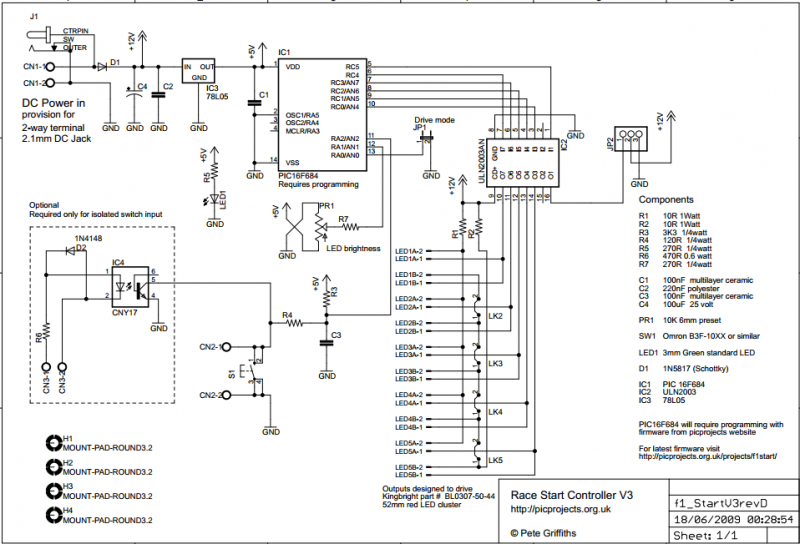
The start switch input connects to the PIC via R3, R4, and C3 which provide immunity to false triggering from electrical noise. If the start switch is located more than a couple of metres from the control PCB it is advisable to use the isolated switch input which offers greater protection against both false triggering and spikes on the input.
The controller also includes an optional isolated switch input. This uses a CNY17 opto-coupler which provides an electrically isolated trigger input for the controller. This allows the start to be triggered from another device such as a computer timing system. It also provides electrical isolation for safety reasons, or can be used to reduce the possibility of false triggering in an electrically noisy environment. Resistor R6 provides current limiting for the LED inside the CNY17 and D2 protects against reverse connection of the power to the isolated input.
The LED modules are driven by a ULN2003A darlington transistor array. The board supports two rows of 5 LEDs with each row using a single current limit resistor (R1/R2). The LEDs are driven with a PWM signal to allow adjustment of the overall brightness. Since all the LEDs in one row share a single current limit resistor, the LEDs are driven one at a time. This means only one LED module is ever actually on but the output scans at ~350Hz so they appear to be on simultaneously. As mentioned above, this reduces the current requirements from just over 2amps for a 10 LED setup to under 500mA. If only a single row of LED modules are used this drops to around 260mA.
The brightness of the LED modules can be adjusted using potentiometer PR1. This feeds a voltage between 0 and 5 volts to the PIC's internal analogue to digital converter. The digitised value is then used to adjust the duty cycle of the PWM output to the LED modules.
JP2 provides a timing start gate output for external equipment. This is an open-collector output that is driven low for a fixed duration at the completion of the LED start sequence. This can be used to trigger an external timing system, release a start gate, or drive another LED cluster. Additional circuitry may be required depending on the specific application. Since it is primarily intended to trigger another device or system at the end of the timing sequence, this output is not driven with a PWM signal. If it is used to drive an LED module, the brightness isn’t adjustable using PR1.
The circuit integrates several key components that enhance its functionality and reliability. The use of a Schottky diode for reverse polarity protection minimizes voltage drop, ensuring efficient power delivery. The 78L05 voltage regulator stabilizes the supply voltage for the microcontroller, which is crucial for consistent performance. The ULN2003A driver allows for the control of high-current LED modules without overloading the microcontroller's output pins. The PWM control method employed allows for dynamic brightness adjustment, enhancing the versatility of the LED clusters in various applications. The inclusion of an opto-coupler for isolated triggering not only adds safety but also allows for integration with various external systems, making the design adaptable for different operational environments. Overall, this circuit design is robust, efficient, and suitable for applications requiring high-brightness LED illumination with precise control capabilities.The circuit described on this page is designed around Kingbright's 52mm LED cluster module which comprises 50 red LEDs in a waterproof housing with a brightness in excess of 16000mcd. In the original version of this project each LED cluster was directly driven and all those LED's required a hefty current with the ten LED cluster version requiring a power supply capable of delivering over 2amps at 12V DC.
The input power to the board can be fed from either the DC Jack or 2-way screw terminal block. These connectors are wired in parallel to give a choice of connection. The positive supply is fed to the rest of the board via D1 which provides protection against a reversed power connection to the board. D1 is a Schottky diode and is used in preference to a standard diode because of its a low forward voltage drop of around 0.25 volts. A 78L05 voltage regulator provides the 5 volt supply for the PIC and a ULN2003A interfaces the PIC outputs to the LED modules. LED1 is connected across the output of the 78L05 to provide a power-on indication.
The start switch input connects to the PIC via R3,R4 and C3 which provide immunity to false triggering from electrical noise. If the start switch is located more than a couple of metres from the control PCB it is advisable to use the isolated switch input which offers greater protection against both false triggering and spikes on the input.
The controller also includes an optional isolated switch input. This uses an CNY17 opto-coupler which provides an electrically isolated trigger input for the controller. This allows the start to be triggered from another device such as a computer timing system. It also provides electrical isolation for safety reasons, or can be used to reduce the possibility of false triggering in an electrically noisy environment. Resistor R6 provides current limiting for the LED inside the CNY17 and D2 protects against reverse connection of the power to the isolated input.
The LED modules are driven by a ULN2003A darlington transistor array. The board supports two rows of 5 LEDs with each row using a single current limit resistor (R1/R2). The LEDs are driven with a PWM signal to allow adjustment of the overall brightness. Since all the LEDs in one row share a single current limit resistor, the LEDs are driven one at a time. This means only one LED module is ever actually on but the output scans at ~350Hz so they appear to be on simultaneously. As mentioned above, this reduces the current requirements from just over 2amps for a 10 LED setup to under 500mA. If only a single row of LED modules are used this drops to around 260mA.
The brightness of the LED modules can be adjusted using potentiometer PR1. This feeds a voltage between 0 and 5 volts to the PICs internal analogue to digital converter. The digitised value is then used to adjust the duty cycle of the PWM output to the LED modules.
JP2 provides a timing start gate output for external equipment. This is an open-collector output that is driven low for a fixed duration at the completion of the LED start sequence. This can be used to trigger an external timing system, release a start gate, or drive another LED cluster. Additional circuitry may be required depending on the specific application. Since it's primarily intended to trigger another device or system at the end of the timing sequence this output is not driven with a PWM signal. If it's used to drive a LED module, the brightness isn't adjustable using PR1.
🔗 External reference
Related Circuits
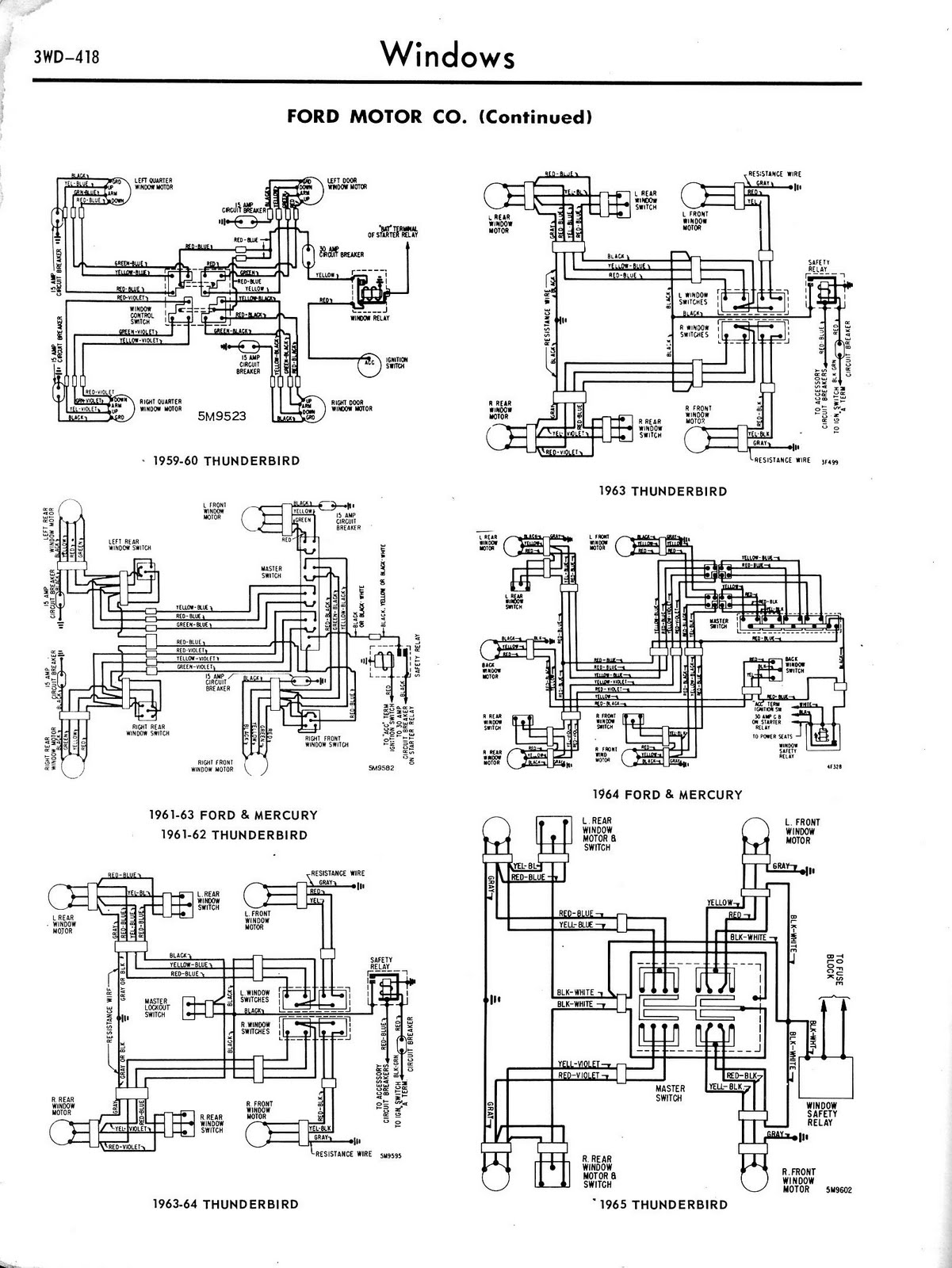
Toyota MR2 Exterior Lights Wiring Diagram Manual PDF Download. The Toyota MR2 Exterior Lights Wiring Diagram Manual provides a comprehensive guide for understanding the wiring configurations associated with the exterior lighting system of the Toyota MR2 model. This manual is...

The circuit illustrated in Figure 3-81 employs a transistor delay circuit to facilitate start-stop cycle control. It can operate in both manual and automatic modes. The circuit is primarily governed by the motor run time circuit, which includes transistors...
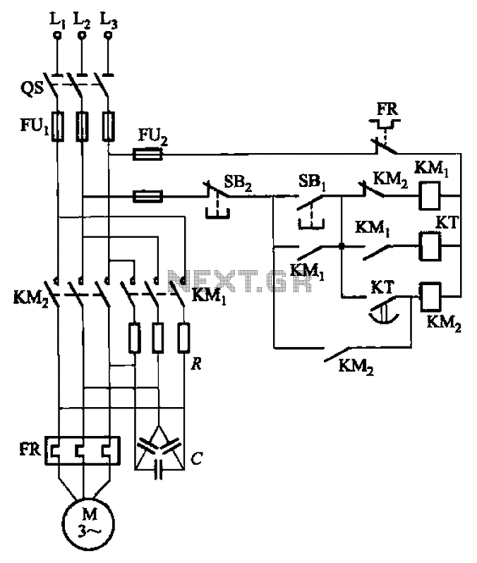
The circuit depicted in Figure 3-35 demonstrates a method for starting a motor that transitions to full voltage through a step-down switching process. This approach provides an uninterruptible power supply, effectively preventing issues related to switching currents that may...

The following plans outline the construction of a compact tracking transmitter that can be detected using an FM broadcast band radio receiver. The transmitter operates on a battery voltage range of 3 volts to 9 volts and has a...
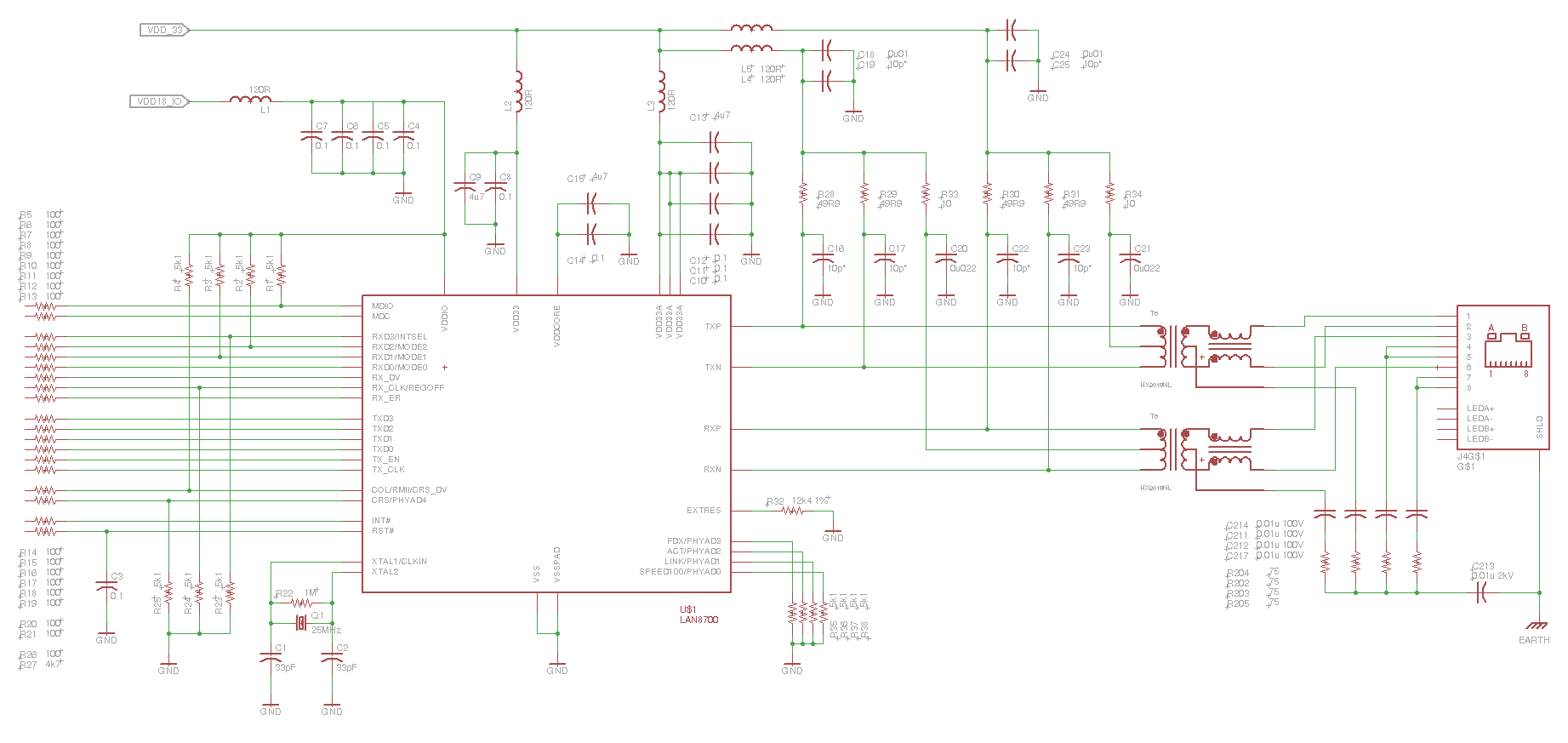
This is the eye diagram for the transmit pair. The receive pair is very similar. It is a LAN8700 PHY, and the MII interface has been effectively disabled, resulting in the PHY transmitting IDLE code sequences. It is forced...

The transistor characteristic curve tracer circuit depicted in Figure 555 illustrates the characteristics of a transistor. It utilizes two voltages: a step wave applied to the base (b) to generate different base currents (Ib), and a sawtooth waveform at...