
555 electrical equipment overload and a phase circuit protection device
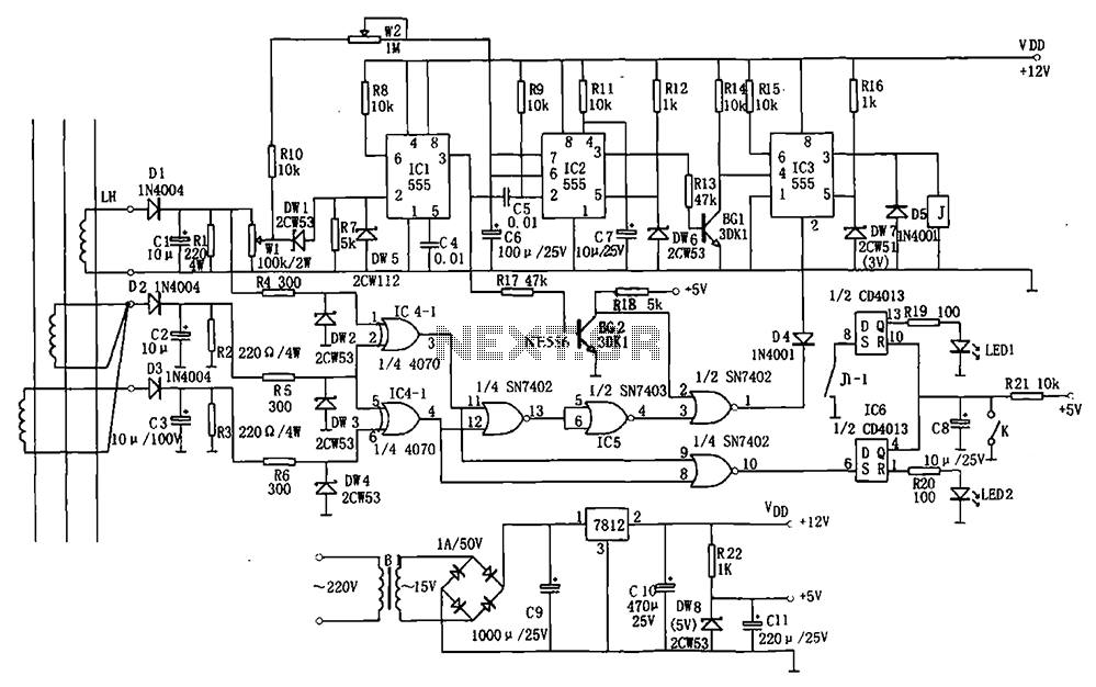
The circuit operates by utilizing a three-phase AC transformer that steps down the AC voltage to a manageable level. The output of the transformer is connected to a rectifier circuit composed of diodes D1, D2, and D3, which converts the AC voltage to a pulsating DC voltage. This pulsating DC is then smoothed using capacitors to provide a stable DC voltage to the rest of the circuit.
The voltage comparators (IC1, DW1, DW5, R7) continuously monitor the DC voltage levels. They ensure that the voltage remains within preset thresholds, which are crucial for the operation of the subsequent components. If the voltage exceeds or drops below these levels, the comparators will trigger an alert or activate protective measures.
The phase failure protection circuit is vital for maintaining operational integrity in three-phase systems. It employs logic gates and flip-flops to monitor the phase currents. The CD4070 (IC4) acts as a NAND gate, while the 7402 (IC5) serves as a NOR gate, allowing for complex logic operations to determine the presence of all three phases. The CD4013 (IC6) is a dual D-type flip-flop that helps to store the state of the phase detection.
In the event of a phase loss, the output from the phase failure protection circuit is sent to IC3, which is responsible for controlling the relay. When a phase is detected as absent, IC3 activates the relay, effectively disconnecting the power supply to prevent damage to the equipment. This relay control circuit is crucial for protecting sensitive electrical equipment from potential overloads or phase imbalances, ensuring safe and reliable operation in industrial environments.
Overall, this circuit design provides a robust solution for electrical equipment protection, combining voltage monitoring, phase detection, and automatic disconnection mechanisms to enhance system reliability and safety. As shown for the electrical equipment overload and phase failure protection circuitry. The device consists of + 12V, + 5V DC power supply, AC transformer, voltage comparators, timers blockade, relay control circuit and phase loss protection circuit. Wherein the DC power supply for the entire circuit DC voltage.The three-phase AC transformer LH current flowing through the coupling proportionally out and were treated D1C1, D2C2, D3C3 rectified filtered Bo Houjia to the voltage comparator (IC1, DW1, DW5, R7) and phase failure protection circuit (IC4, IC5, IC6). By the lack of IC4 (CD4070), IC5 (7402), IC6 (CD4013) and other components of phase protection circuit for detecting and determining the presence or absence of three-phase current, if one phase, set the IC3, relay pull-J together, the power supply is disconnected for phase protection.
Related Circuits
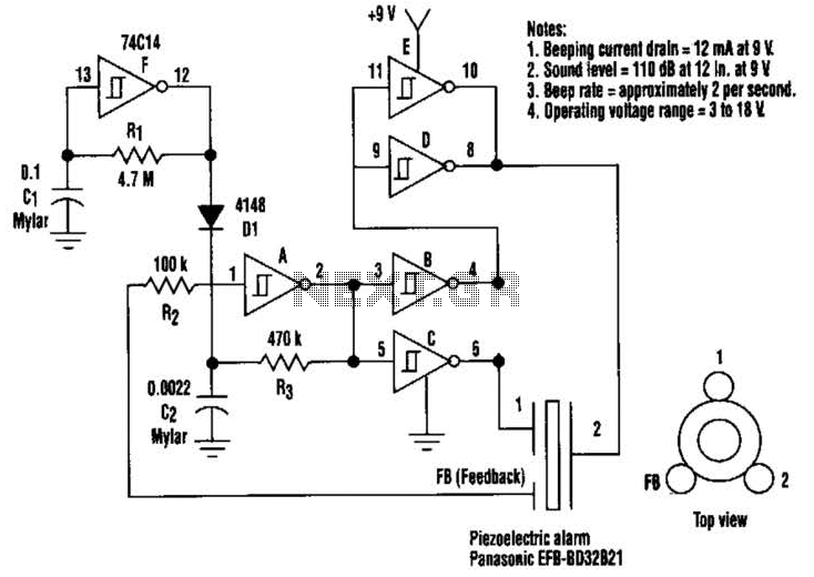
This circuit generates a loud sound of 110 dB using a 9 V power supply. It incorporates a single 74C14 (CD40106B) CMOS hex inverting Schmitt-trigger IC, which is utilized with a piezoelectric device that includes a feedback terminal. The...
Figure 7-2 illustrates the FSK (Frequency Shift Keying) signal demodulation circuit, which is built using a digital phase-locked loop. This circuit features two oscillators operating at distinct frequencies: crystal oscillator X with a frequency of 983.04 kHz and crystal...
The CD4001 quad 2-input NOR gate is a highly versatile integrated circuit (IC) that can be utilized in numerous applications. This example demonstrates its use in a simple alarm system. The recommended power supply voltage for the CD4001 ranges...
The following diagram is for the main circuit of the motor driver. A testing version is shown near the end of this page. It is laid out differently and shows the SN7474 in logic block form and LEDs are...
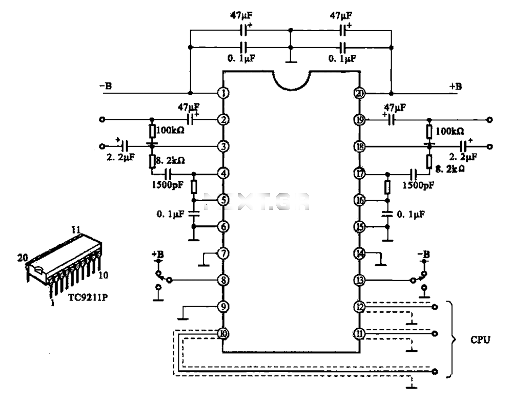
A typical electronic volume control circuit is commonly used in stereo audio devices connected through a computer (CPU). The circuit adjusts the volume of stereo signals via input and output pins. Control signals are sent to the CPU (including...
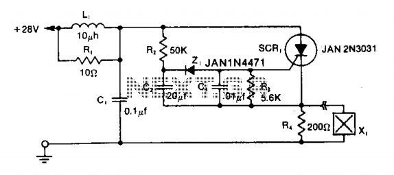
The LRC input network limits the anode dv/dt to a safe value below 30 V/μs. Rl provides critical damping to prevent voltage overshoot. While a simple RC filter section could be used, the high current required by the squib...