
Stepper Motor Driver Circuit

The motor driver circuit is designed to control a stepper motor using a series of clock pulses to sequentially energize the motor coils. The main component in this circuit is the SN7474, which is a dual D-type flip-flop that serves as a logic control element. The flip-flop configuration allows for the storage and manipulation of binary data, enabling precise control over the motor's stepping sequence.
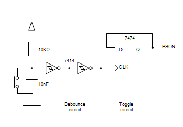
The diagram includes a representation of the clock signal, depicted by a blue line, which indicates the timing for switching the motor coils. This clock pulse is critical as it determines the speed and direction of the motor's rotation. The motor typically has a common wire and four coil leads, which are connected to the outputs of the SN7474. The arrangement of these connections is essential for proper motor operation, as it ensures that the coils are energized in the correct sequence to achieve the desired stepping motion.
LEDs are incorporated into the circuit to provide visual feedback on which coils are currently energized. This feature is particularly useful for testing and debugging purposes, allowing an engineer to observe the operation of the circuit in real-time. The presence of a filter capacitor is also noted, which serves to smooth out voltage fluctuations and reduce noise in the power supply, ensuring stable operation of the motor driver.
Overall, this motor driver circuit schematic is a practical solution for controlling stepper motors in various applications, providing a clear and effective means to manage motor functions through digital logic.The following diagram is for the main circuit of the motor driver. A testing version is shown near the end of this page. It is laid out differently and shows the SN7474 in logic block form and LED`s are used to indicate the motor coils being switched. The blue line on the drawing is the path that the CLOCK pulses that drive the circuit follow. The stepper motor would not be connected as shown on the schematic as the motors usually have a common and four coil leads. Also, the filter capacitor 🔗 External reference
Related Circuits
Building circuits to interface an Amiga A1200 to a PC AT/ATX power supply and tower case. To create a reliable interface between an Amiga A1200 and a PC AT/ATX power supply and tower case, it is essential to design a...
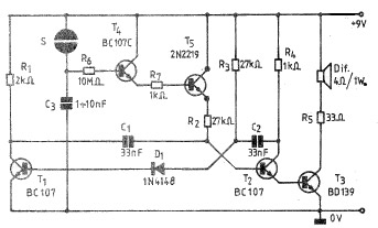
A simple and practical electronic bell circuit can be constructed using the provided schematic diagram. This circuit can function as a doorbell or an alarm system. It utilizes only a few transistors along with several common components. The circuit...
The PIC16F84A digital thermometer circuit is constructed primarily using a temperature sensor along with various discrete components. The PIC16F84A microcontroller serves as the core processing unit of the digital thermometer circuit. It is equipped with an 8-bit architecture and supports...
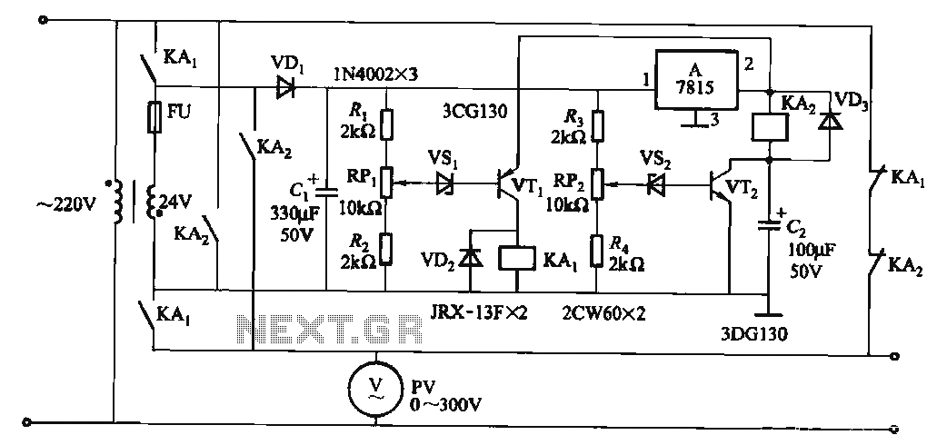
When the input voltage is in the range of 170-260V AC, the output AC voltage falls between 187-231V. The transformer ratio is k = 24/220 = 0.11. If the input voltage drops below 170V, relay KAi activates (adjusted by...
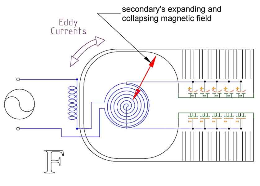
Arcing completes a circuit -- closes a system -- between two voltage potentials. When arcing occurs, two oppositely charged static voltage potentials can cancel each other out. The arcing problems that occur are usually between two electrically isolated voltage...
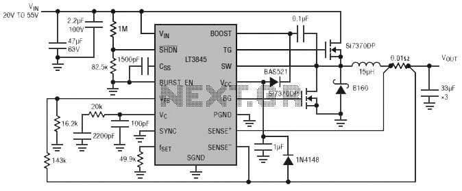
Burst Mode operation maintains high efficiency at light loads by reducing IC quiescent current to 120 µA. Light load efficiency is also improved with the reverse inductor current inhibit function, which supports discontinuous operation. Additional features include an adjustable...