
555 Electronic Metronome Circuit
The metronome circuit is a timing device that generates a regular pulse signal, typically used in music practice to maintain a steady tempo. The 555 timer IC, a versatile and widely used component, can be configured in astable mode to produce this pulsing output. The configuration provided by ON Semiconductor and National Semiconductor highlights the importance of proper component placement and values in achieving the desired frequency output.
In the proposed circuit, the connection of pins 2, 6, and 7 is crucial. By separating these pins and incorporating resistors Ra and Rb, the timing characteristics of the circuit can be fine-tuned. Resistor Ra connects the supply voltage to pin 7, ensuring the timing capacitor can charge through this resistor. Resistor Rb, positioned between pin 7 and pin 6, influences the discharge path of the timing capacitor, allowing for control over the frequency of oscillation.
The capacitor between pin 6 and ground plays a significant role in defining the timing intervals. The output frequency formula, f = 1.44 / C[Ra + 2Rb], indicates that adjusting the values of Ra and Rb, as well as the capacitor C, will directly affect the frequency of the metronome. It is essential to use precise component values to achieve the desired frequency range.
The recommendation for a 0.01 µF capacitor between pin 5 and ground serves to stabilize the voltage at pin 5, which is the control voltage pin of the 555 timer. This capacitor helps filter any noise that may affect the timer's operation, ensuring a more stable output frequency.
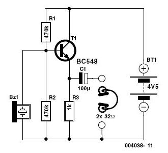
Regarding the audio output, the use of an LM386 audio amplifier is appropriate for boosting the sound level produced by the metronome circuit. However, the choice of loudspeaker must align with the amplifier's specifications to prevent distortion or damage. It is advisable to review the maximum power rating of the loudspeaker to ensure compatibility with the LM386, which can deliver up to 1 watt of output power. If the sound level remains low, consider adjusting the gain settings on the LM386 or exploring alternative loudspeakers with higher sensitivity.I have assembled the metronome circuit several times and it did not work. Two 555 manufacturers websites (ON Semiconductor and National Semiconductor) propose circuits that differ from yours in that pins 2/6/7 are not joined together but there is a resistor Ra between +Vcc and pin 7, a resistor Rb between pin 7 and pin 6 (= pin 2 ) and the capacitor is between pin 6 and ground. The output frequency is f=1. 44/C[Ra+2Rb]. Both manufacturers ask for a 0. 01 f capacitor between pin 5 and ground. It would have been helpful to specify the maximum power rating of the loudspeaker. The sound level I am getting is quite low and am trying to use an LM386 audio amplifier. Any suggestion Mula ±umiri 🔗 External reference
Related Circuits
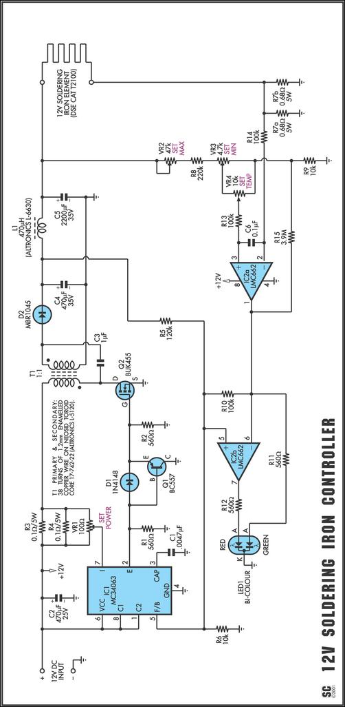
One reason commercial soldering stations are costly is that they typically require soldering irons with built-in temperature sensors, such as thermocouples. This circuit removes the necessity for a specialized sensor by detecting the temperature of a soldering iron heating...
The circuit was designed to create an electronic siren to produce an alert sound in emergency situations or any circumstances that require its usage. The 4011 is a quad 2-input NAND gate integrated circuit, characterized by minimal voltage supply...
This toggle circuit utilizes two 555 timers configured as inverters. Pins 2 and 6 serve as the threshold and trigger inputs for the first timer, while pin 5 provides the output. The output at pin 5 will consistently reflect...
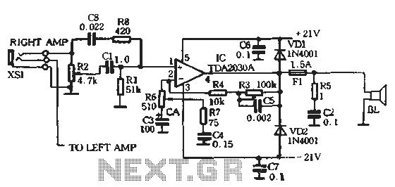
The circuit comprises two main components: the Lisheng power amplifier and the rectifier filter section. The stereo audio power amplifier circuit diagram, depicted in Figure 5-85, illustrates only one channel, with the other channel being identical. The audio signal...
This is a simple two-transistor lamp flasher circuit that can be used to flash a 6-volt lamp. The circuit is compact and can be easily fitted into a small enclosure. It utilizes two transistors: one is an NPN BC549,...
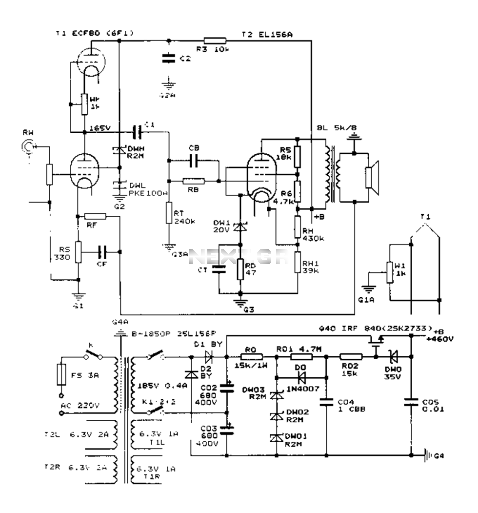
The Danji mellow sound is characterized by its transparent and natural quality, offering a sweet and sincere listening experience that is tireless over long durations and rich in humane color. Tube amplifiers have become an audiophile's companion and are...