
Drying the motor winding circuit current imbalance
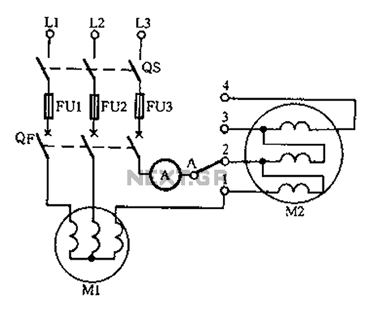
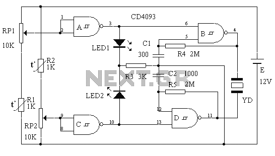
The circuit diagram is designed to monitor the current flowing through the windings of a motor used in drying applications. This imbalance detection is crucial for ensuring the motor operates efficiently and safely. The schematic typically includes current sensors, which can be Hall effect sensors or shunt resistors, connected to an operational amplifier (op-amp) configured as a differential amplifier. This setup allows for precise measurement of the current in each winding.
The output from the op-amp is then fed into a microcontroller or a comparator circuit. The microcontroller processes the current data and compares the values from the different windings. If an imbalance is detected, it can trigger an alarm or a shutdown mechanism to prevent damage to the motor.
Additionally, the circuit may include indicator LEDs to provide visual feedback on the status of the motor winding currents. A power supply circuit is also essential to ensure that all components receive the necessary voltage levels for operation.
In summary, this motor winding current imbalance detection circuit is a critical component for maintaining the reliability and safety of drying motors, ensuring that they function within acceptable parameters and preventing potential failures due to uneven current distribution. Below is a circuit diagram of the motor winding current imbalance drying:
Related Circuits
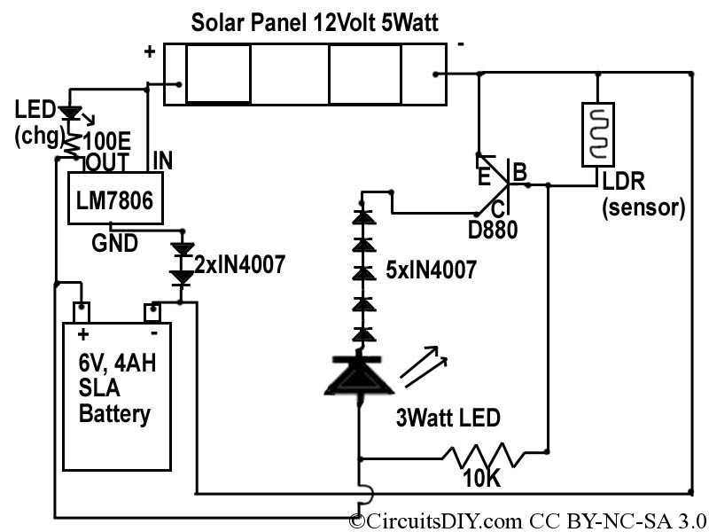
This document discusses a simple solar LED circuit. Solar panels range from 12 volts and 3 watts to larger sizes. To store energy, a 12-volt battery is required. The preferred choice is a sealed lead-acid (SLA) sealed maintenance-free (SMF)...
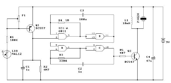
This light alarm schematic circuit is designed using common electronic components, as illustrated in the circuit diagram below. The light alarm circuit will activate an alarm as soon as the drawer is opened and light falls on the Darlington...

This circuit exhibits an exceptionally fast high-frequency response, as demonstrated by applying a 100 kHz square wave to the input. All graphs were produced using Tina Pro. The circuit's design is optimized for high-frequency applications, showcasing rapid response times that...
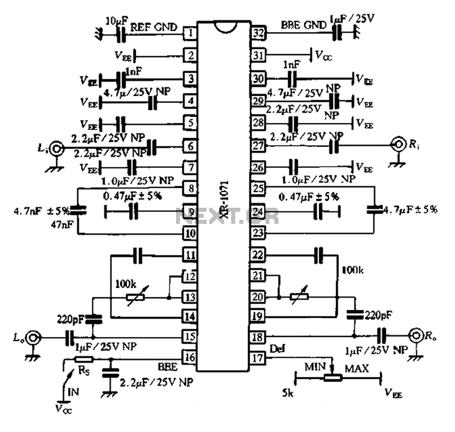
The 1071 touch utilizes audio enhancement technology, introducing a high-resolution two-channel stereo enhancement processing chip designed to improve product performance. It aims to enhance stereo sound systems, allowing various audio sources to exhibit a strong spatial presence. The chip...

This is a simple design of an audio level meter. The circuit utilizes a single integrated circuit (IC) and a minimal number of external components. It is based on the LM3915, which functions as the controller for the audio...
This circuit is a two-way alarm system that utilizes a Schmitt IC, featuring responsive sound and light indicators. It is compact, energy-efficient, and consists of only 13 components, making it a cost-effective solution. The circuit is divided into two...