
555 How can I make a 15 minute egg timer circuit

To design a timer circuit that meets the specified requirements, a 555 timer IC can be utilized in a monostable configuration for generating timed intervals. The circuit will be initiated by a push button that triggers the timer. When the button is pressed, the timer will start, lighting up the three LEDs connected in parallel.
The 555 timer can be configured to produce a high output for a duration of 5 minutes. This can be achieved by selecting appropriate resistor (R) and capacitor (C) values according to the formula:
\[ T = 1.1 \times R \times C \]
To achieve a timing period of 5 minutes (300 seconds), suitable values for R and C should be calculated. For example, using a capacitor of 1000 µF and a resistor of 330 kΩ would yield a timing interval close to 5 minutes.
To control the LEDs, a simple transistor switch can be used. Each LED can be connected to the collector of a transistor, which is controlled by the output of the 555 timer. After the first 5 minutes, the timer can be configured to send a pulse to turn off one LED, using a counter circuit or a simple shift register to track how many LEDs have been turned off.
After 15 minutes, the timer output can trigger a solenoid to ring a bell. This can be achieved by connecting the output of the timer to a relay that activates the solenoid. The relay should be rated for the solenoid’s voltage and current requirements to ensure proper operation.
In terms of circuit design, the schematic should include:
1. A push button connected to the trigger pin of the 555 timer.
2. A resistor and capacitor connected to the appropriate pins to set the timing interval.
3. A transistor for each LED to control their states based on the timer output.
4. A relay connected to the timer output for activating the solenoid.
This approach provides a clear pathway to designing a functional timer circuit that meets the specified requirements, leveraging the familiar 555 timer while incorporating additional components for LED control and solenoid activation.To do this, I want to push a button to initiate the timer, which will then light 3 x leds. After each 5 minute segment is up, one of the LEDs should go out. Finally, when 15 mins is up, I want to ring a bell (just once) using a solenoid. Trouble is - I don`t know where to start! My background in more in computer programming - so I understand the logic required to do it, just not how! (I`ve put circuits together in the past, but always using someone elses schematic - I`m not sure where to start in terms of designing my own. ) I`m not looking for someone to design it for me (though it might help!) but for an idea of where to start figuring out how to do this.
Have had a look at some 555 based egg timer circuits, but don`t know how you set the time periods on them. Have knocked up a vague schematic - does it look like I`m heading in the right direction If this does what I think it does it should begin with three LEDs switched on, then with each clock pulse knock an LED off until they`re all off - then it should reset.
🔗 External reference
Related Circuits
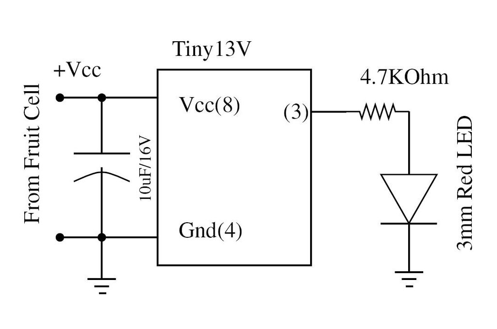
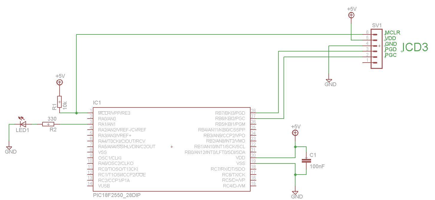
Wire the circuit diagram shown here on a breadboard. The choice of V type of AVR is important. For example, Tiny13V is very appropriate for such an application. To successfully implement the circuit diagram on a breadboard, several considerations must...
The text of the Arduino reference is licensed under a Creative Commons Attribution-ShareAlike 3.0 License. Code samples in the reference are released into the public domain. The Arduino platform is an open-source electronics prototyping environment that enables users to create...
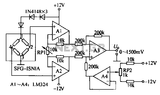
This is a measurement circuit designed to measure forces ranging from 0 to 1500 grams, producing an output voltage of 0 to 1500 millivolts (mV) with a sensitivity of 1 mV per gram. The circuit is powered by a...
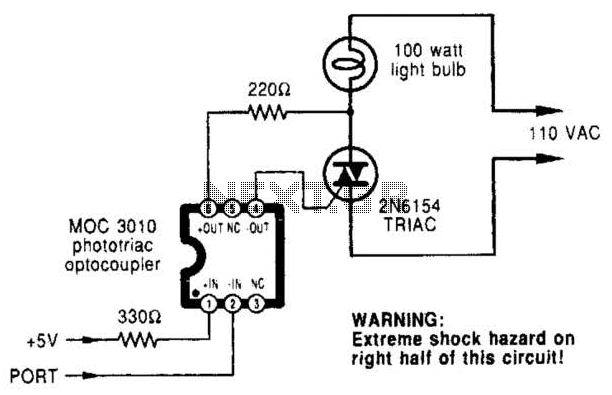
A microcomputer-to-triac interface utilizes a phototriac optoisolator to safely isolate logic signals, allowing direct control of high-power loads. This circuit can function as either an on/off switch or a proportional phase control, depending on the input waveforms and the...
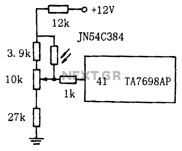
The circuit for automatic brightness adjustment in a television utilizes a photosensitive resistor and a contrast potentiometer connected to an intermediate stage. The photosensitive resistor varies its resistance based on light intensity, causing changes in the potential at the...
The LED blinks as expected, then pauses for an indefinite duration, flashes again a different number of times, and turns off again, displaying no discernible cyclic behavior. It activates without any external input, indicating that there is likely no...