
Pressure measurement circuit diagram

The measurement circuit is designed for precise force sensing applications, utilizing a force sensor that operates within a specified range. The power supply circuit is critical for ensuring stable operation, where the initial 12V supply is reduced to approximately 10V to power the operational amplifiers effectively. The use of diodes for voltage reduction is a simple yet effective method to achieve the desired voltage level while protecting the circuit from potential over-voltage conditions.
The instrumentation amplifier is a key component of this circuit, as it amplifies the small differential voltage produced by the force sensor. The configuration of A1, A2, and A3 allows for high common-mode rejection, which is essential in applications where noise might interfere with the signal. The direct connection of the differential input terminals to the force sensor ensures that the output is a true representation of the force applied.
The voltage follower configuration of A4 serves to buffer the output, preventing loading effects that could distort the measurement. The incorporation of potentiometer RP2 allows for fine-tuning of the output when no force is applied, ensuring that any offset due to the sensor or amplifier characteristics can be corrected. This adjustment is crucial for achieving accurate measurements, particularly in high-precision applications.
Furthermore, the output voltage can be calibrated using potentiometer RP1, allowing the user to set the output to a specific value at the maximum force of 1500 grams. This calibration process is vital for ensuring that the system provides reliable and consistent measurements across its operational range.
In terms of component selection, the recommendation to use metal film resistors with a tolerance of 1% or better is significant. These resistors provide stable performance and minimize drift, which is critical in maintaining the accuracy of the instrumentation amplifier over time and varying environmental conditions. The pairing of resistors in the amplifier circuit further enhances precision by ensuring that any discrepancies in resistance values are minimized.
Overall, this measurement circuit is well-suited for applications requiring accurate force measurement, such as in industrial automation, robotics, or laboratory settings. Its design emphasizes stability, precision, and adaptability, making it a robust solution for various force sensing needs.It is a measurement circuit, when the force is 0 ~ 1500g time. U. Output O ~ 1500nN (sensitivity ImV / g). Powered by 12V power supply with disabilities, the force sensor consists of 12V (about 10V) power supply after three diode buck. A1 ~ A3 composed of the instrumentation amplifier whose differential input terminal directly, feet connected to the force sensor feet.
A4 connected as a follower, the input voltage potentiometer RP2, whose role is to eliminate zero output, that is, when the force is zero, if the bridge or unbalanced output amplifiers have offset voltage can be adjusted RP2. The output U. -ov. Adjust RP1 (adjusted magnification) can be at full scale 1500g force that Uo = 1500mV. To ensure the accuracy of the instrumentation amplifier, the resistance should be used metal film resistors, the resistors A1 ~ A3 accuracy of 1% or better after pairing.
Related Circuits

The following circuit is a PC thermometer utilizing the DS1621. Features include the ability to plug into any available PC COM port, a temperature range of -20 to 125°C, and the capability to display temperatures in both Celsius (°C)...
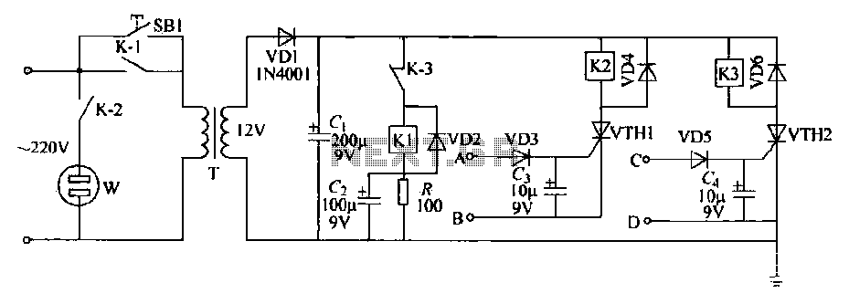
This schematic circuit features two alarm outputs controlled by a timer using thyristors. The system can be turned on or off and will shut down after the power supply is interrupted. It employs a transformer on the primary side...
S1 and S2 are normally open, push-to-close, momentary switches. The diodes can be red or green and serve solely as indicators for direction. The TIP31 transistors may need to be adjusted based on the motor specifications. It is important...
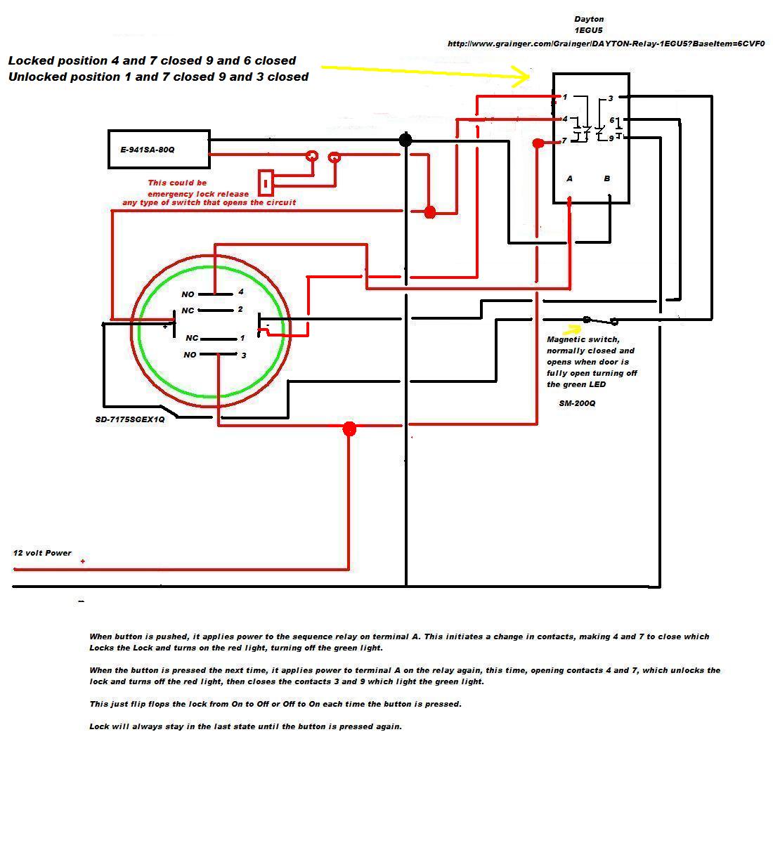
A 12V DC electromagnetic lock is designed with a push-to-lock and push-to-unlock mechanism using an existing LED indicator/switch. The switch should display a green light when unlocked and red when locked. The LED indicator/switch is the SD-7175SGEX1Q, which is...
The refrigerator turned on, causing the lights to brighten. Initially, it seemed like an illusion, but after observing multiple cycles, the phenomenon persisted. When the microwave was activated, the lights dimmed. The refrigerator's operation appeared to influence the brightness...
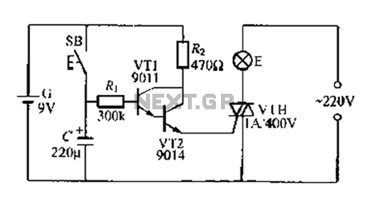
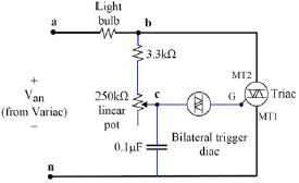
A delay circuit utilizing an electric lamp. Normally, the thyristor VTH remains off, and the lamp E does not illuminate. The lamp turns on when needed, controlled by the FSH, with the VT1 and VT2 components forming a composite...