
555 IC For 12V Lead Acid Battery Desulphator Circuit

The circuit diagram for a 6/12/24V Lead Acid Battery Charger is designed to efficiently charge lead-acid batteries of varying voltages. The primary function of this circuit is to convert the input AC voltage into a suitable DC voltage that can be used to charge the batteries while ensuring the safety and longevity of the battery cells.
At the core of the circuit is a high-voltage pulse generator, which is responsible for producing the necessary charging pulses. This pulse generator typically consists of a transformer, rectifier diodes, and a smoothing capacitor. The transformer steps down the input AC voltage to a lower level suitable for charging the battery. The rectifier diodes convert the AC voltage to pulsating DC, which is then smoothed by the capacitor to provide a more stable DC output.
The circuit also incorporates a voltage regulator to prevent overcharging, which can be detrimental to lead-acid batteries. This regulator monitors the output voltage and adjusts the charging current accordingly, ensuring that the battery receives the correct voltage level. Additionally, a current limiting feature may be included to restrict the charging current to a safe level, further protecting the battery from damage.
For versatility, the charger can be designed with selectable voltage outputs (6V, 12V, and 24V) using a switch or jumper settings. This allows the charger to be used with different battery configurations without the need for multiple chargers.
Safety features, such as fuses and thermal protection, are critical in this design to prevent overheating and potential hazards during the charging process. Overall, this circuit serves as an effective solution for charging lead-acid batteries, ensuring optimal performance and extending the life of the batteries.The following circuit shows about 6/12/24V Lead Acid Battery Charger Circuit Diagram. Features: ssentially a high-voltage pulse generator which is .. 🔗 External reference
Related Circuits
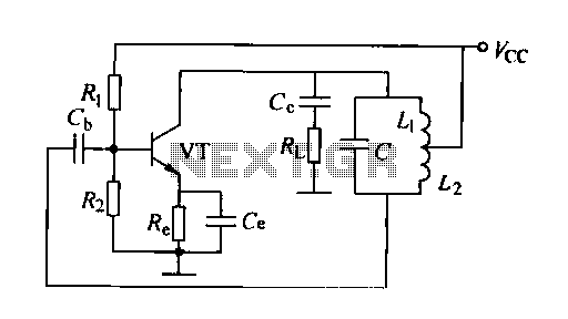
A feedback oscillator circuit utilizing inductance is presented, featuring the 3DG3 transistor. The component parameters reference values include: 1) transistors 3DG6, 2) resistances R1 at 91 kΩ, R2 at 11 kΩ, and R3 unspecified, 3) capacitance values of C...
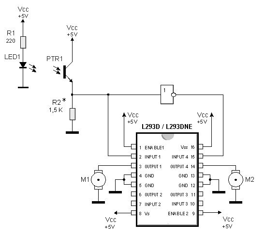
By utilizing logic chips, the behavior of a robot can be enhanced, allowing for the implementation of more complex algorithms. Logic chips, also known as logic gates or digital logic integrated circuits, are fundamental components in digital electronics that perform...
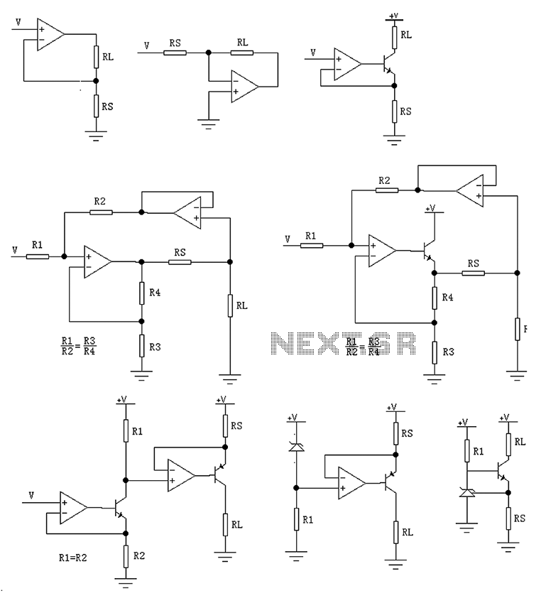
The circuit is designed to provide several constant current outputs to the load resistor RL. The first RL is floating and is rarely utilized. The second RL serves as a virtual ground and is not commonly used either. The...
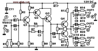
This electronic circuit is a video signal amplifier that provides a broad bandwidth amplifier with a capacity of 5 MHz. It is designed to take video signals from a VCR and amplify them adequately to drive up to three...
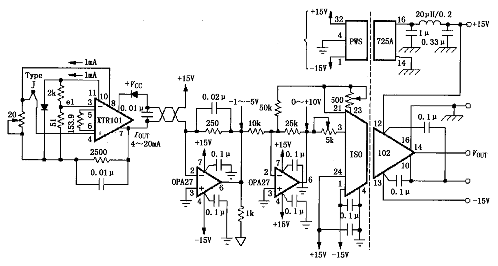
The circuit depicted in the figure features the ISO102 and XTR101 components, forming an isolated remote transmitter circuit equipped with isolated thermocouple cold-junction compensation. The circuit comprises four main parts: the current loop amplifier XTR101, the isolation amplifier ISO102,...
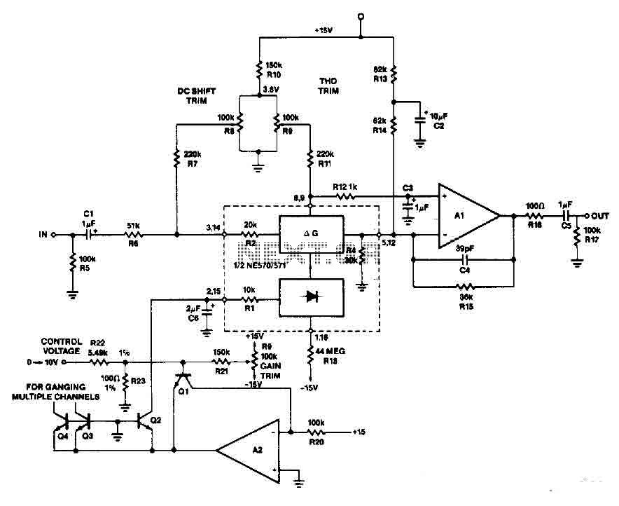
An operational amplifier along with transistors Q1 and Q2 forms an exponential converter to produce an exponential gain control current, which is fed into the rectifier. A reference current of 150 pA, with a voltage of 15 V and...