
simple line follower robot logic circuits

Logic chips, also known as logic gates or digital logic integrated circuits, are fundamental components in digital electronics that perform logical operations on one or more binary inputs to produce a single binary output. These chips can be combined in various configurations to create more sophisticated decision-making processes within robotic systems.
For instance, a combination of AND, OR, and NOT gates can be used to develop a simple control system that allows a robot to respond to environmental stimuli. By integrating multiple logic chips, a robot can be programmed to execute complex tasks such as obstacle avoidance, pathfinding, and adaptive learning based on its interactions with the surroundings.
To design a circuit using logic chips for a robot, one might start with a truth table that defines the desired behavior. This table will outline the inputs (such as sensors detecting obstacles) and the corresponding outputs (such as motor controls for movement). The logic functions derived from the truth table can then be implemented using various logic gates, which can be arranged on a breadboard or printed circuit board (PCB).
In addition to basic logic operations, flip-flops can be incorporated to create memory elements that allow the robot to retain state information between actions. This enables the implementation of more advanced algorithms, such as state machines or finite automata, which can significantly enhance the robot's operational capabilities.
Overall, the use of logic chips in robotic design not only simplifies the implementation of complex behaviors but also allows for scalability and adaptability in the robot's functionality.Using logic chips we can make the robot`s behavior more interesting and can implement more complex algorithms.. 🔗 External reference
Related Circuits
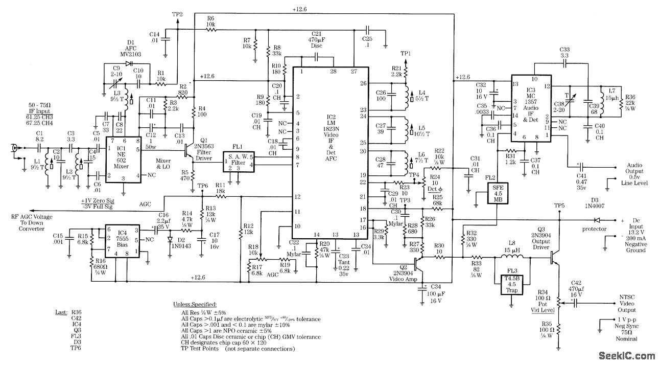
Radio-frequency schematics (also see NE602 datasheet and application note). This page contains electronic circuits related to RF receivers. This index features a broad collection of RF receiver circuits. Radio-frequency (RF) schematics are essential for designing and implementing circuits that operate...
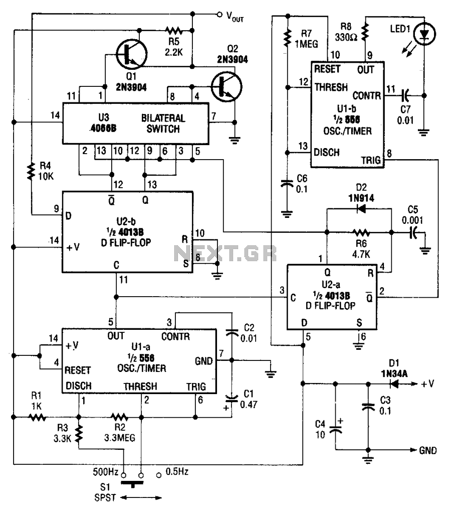
The pulser generates pulses at a user-selected frequency of 0.5 or 500 Hz, with a pulse width of about 5 ms. If the input to be pulsed is already being driven high or low by another output, the pulser...

The following circuit is a power amplifier circuit for an FM transmitter with an output power of 30 watts. The power amplifier circuit utilizes a power transistor of type 2SC1946A. The FM transmitter operates with a 13.8-volt DC power...

A voltage comparator is a device that compares the voltages at its two inputs and generates an output based on the comparison. It produces a high output when the positive input exceeds the negative input and a low output...
The circuit diagram presented is for a compact mini audio power amplifier that operates with a DC supply voltage ranging from 4.5 volts to a maximum of 18 volts. This amplifier utilizes the TDA1015 integrated circuit, produced by NXP...
The following text describes construction, testing and use of an electronic telephone line simulator of my own design. This self-build project can simulate a telephone call / connection between any two local telephone devices. This for a fraction of...