
555 IC PWM Motor Control with Current Limiter
The described circuit employs a MOSFET H-bridge configuration, which is essential for controlling the speed and direction of DC motors efficiently. The use of N-channel MOSFETs for the lower rail is advantageous due to their lower on-resistance compared to P-channel devices, resulting in reduced power losses and improved thermal performance. Conversely, P-channel MOSFETs are employed for the upper rail to facilitate high-side switching, which is crucial for maintaining the desired motor operation.
The TC4469 driver is integral to this design, as it provides the necessary gate drive signals to the MOSFETs, ensuring rapid switching and efficient control. The inclusion of a series resistor mitigates potential oscillations in the gate signal, which can lead to undesired switching behavior and increased electromagnetic interference (EMI). The transition time management is particularly important in applications requiring precise motor control.
For applications where motor voltages exceed 12VDC, the addition of a resistor divider and a level-shifting transistor allows for a stable 15VDC gate drive. This ensures that the upper rail MOSFETs are adequately turned ON to handle higher voltages without risking damage. The use of a linear regulator to derive the gate drive voltage from the motor supply is a practical solution, given the low current requirements of the driver ICs.
Zener diodes are recommended for gate protection against transient voltage spikes, which can occur during motor operation. These diodes clamp the voltage to safe levels, thus preserving the integrity of the MOSFET gates. The gate-to-source capacitors play a pivotal role in maintaining the OFF state of the upper MOSFETs during rapid changes in the lower MOSFET state, effectively preventing unwanted turn-on due to high dV/dT conditions.
Current sensing is facilitated by a sense resistor in the ground leg of the H-bridge, enabling real-time monitoring of motor current. This feature is crucial for implementing current limiting strategies, ensuring that the motor operates within safe parameters. The filtered current signal can be used to disable PWM generation when excessive current is detected, thus protecting the motor and the driver circuit from potential damage. Overall, this H-bridge design provides a robust solution for dynamic motor control applications.To provide rapid motor speed changes and motor direction reversal, four outputs drive a MOSFET H-bridge. N-channel devices are the lower rail power MOSFETs and P-channels are the upper MOSFETs. All of them are driven by the TC4469. A small series resistor helps prevent gate oscillation and slows transition time in the lower rail devices, helping t
he upper device to stay OFF. A resistor divider and low-cost level shift transistor can be added easily and economically to maintain a 15VDC gate drive for the upper rail MOSFETs for motor voltages over 12VDC. A simple linear regulator can power them from the positive motor supply when it is above 15VDC since the ICM7555 and TC4469 need negligible current.
To help protect the gates from supply transients, we can use a Zener diodes. When the lower MOSFET in the same leg turns ON , causing a high dV/dT, gate-to-source capacitors help keep the upper MOSFETs OFF . The other way to help that situation is keeping the upper MOSFET gate drive impedance low in the OFF state.
An easy way to sense motor current, pulse by pulse, regardless of forward or reverse motor rotation is provided by a sense resistor in the ground leg of the H-bridge. To inhibit PWM generation if motor current exceeds the allowed value, this signal is filtered and applied to the ICM7555.
[Microchip Application Notes] 🔗 External reference
Related Circuits
The TPS6420x controller is designed to operate with one to three series-connected cells or from a 3.3 V or 5 V supply obtained from a USB port. The TPS6420x is a highly versatile power management controller that facilitates efficient voltage...
A buzzer circuit utilizes a PIC microcontroller to drive a piezo buzzer. The microcontroller is a low-power processor that is ideal for portable and compact devices where battery conservation is essential. The buzzer circuit employs a PIC microcontroller, which serves...
This circuit produces the sound of a beeper like the one in pagers which produces a "beep-beep" sound. Basically the circuit consists of a 555 timer oscillator which is turned ON and OFF periodically. The first IC (left) oscillates...
Have you verified whether you can see the zero crossings on your input pin? It may be beneficial to write a sketch that toggles the LED on pin 13 every 50 or 60 zero crossings. This should result in...
This hybrid circuit uses a mixture of transistors, an IC and a relay and is used to automatically open or close a pair of curtains. Using switch S3 also allows manual control, allowing for curtains to be left only...
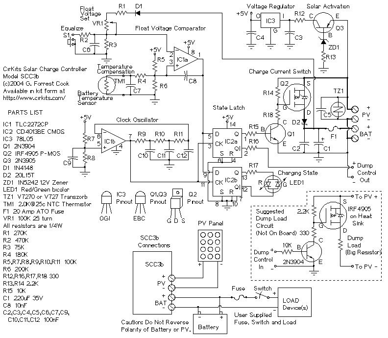
SCC3 12 Volt 20 Amp Solar Charge Controller. A kit with the circuit board and parts for this circuit is available from CirKits. SCC3 - 12 Volt 20 Amp Solar Charge Controller (C) G. Forrest Cook June. The SCC3 Solar...
Warning: include(partials/cookie-banner.php): Failed to open stream: Permission denied in /var/www/html/nextgr/view-circuit.php on line 713
Warning: include(): Failed opening 'partials/cookie-banner.php' for inclusion (include_path='.:/usr/share/php') in /var/www/html/nextgr/view-circuit.php on line 713