
SCC3 12 Volt 20 Amp Solar Charge Controller

The SCC3 Solar Charge Controller is designed to manage the charging of batteries from a solar panel system, specifically optimized for a 12 Volt configuration with a maximum output current of 20 Amps. This device is essential for preventing overcharging and ensuring the longevity of the battery bank in solar applications.
The charge controller operates by regulating the voltage and current coming from the solar panels to the batteries. It utilizes pulse width modulation (PWM) technology to efficiently manage the charging process. The controller features multiple stages of charging, including bulk, absorption, and float stages, which help to optimize battery performance and health.
The circuit board available from CirKits includes all necessary components such as MOSFETs for switching, capacitors for smoothing the output, and diodes for preventing reverse current flow. Additionally, the design incorporates LED indicators to provide real-time feedback on the charging status and battery condition.
Installation of the SCC3 requires connecting the solar panel input, battery output, and load terminals, ensuring that all connections are secure and correctly oriented to prevent damage. The controller is designed for easy integration into existing solar setups, making it an ideal choice for both amateur and professional solar energy systems.
Overall, the SCC3 Solar Charge Controller is a robust solution for effective solar energy management, providing reliability and efficiency for renewable energy applications.SCC3 12 Volt 20 Amp Solar Charge Controller. A kit with the circuit board and parts for this circuit is available from CirKits. SCC3 - 12 Volt 20 Amp Solar Charge Controller (C) G. Forrest Cook June. 🔗 External reference
Related Circuits
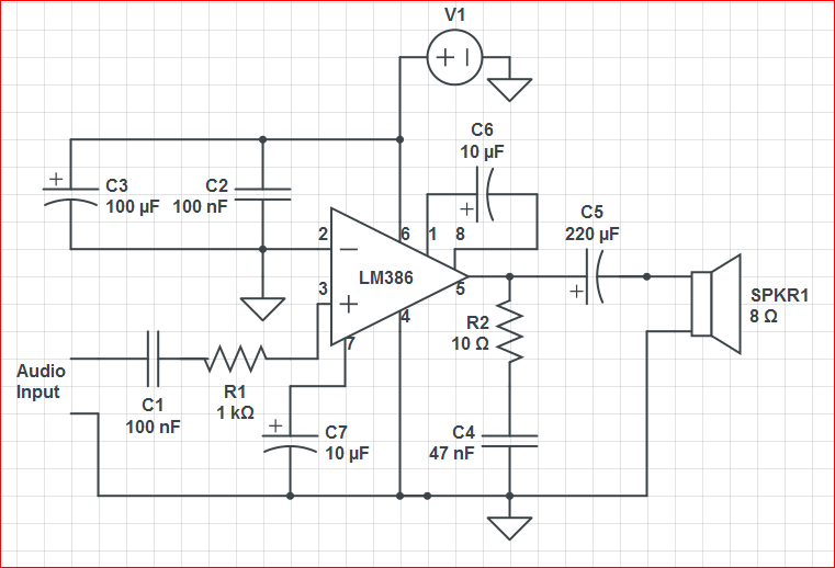
Initially, the circuit was connected to a 9V battery, which registered approximately 8.3 volts on a multimeter, within the operating voltage range for the LM386 as indicated in its datasheet. The output was characterized by significant noise, including crackling...
Using a switch to power up your microcontroller projects may not be a good idea if you need to "wake" the PIC during some events. For example: A metal detector sends a pulse indicating a car is ready to...
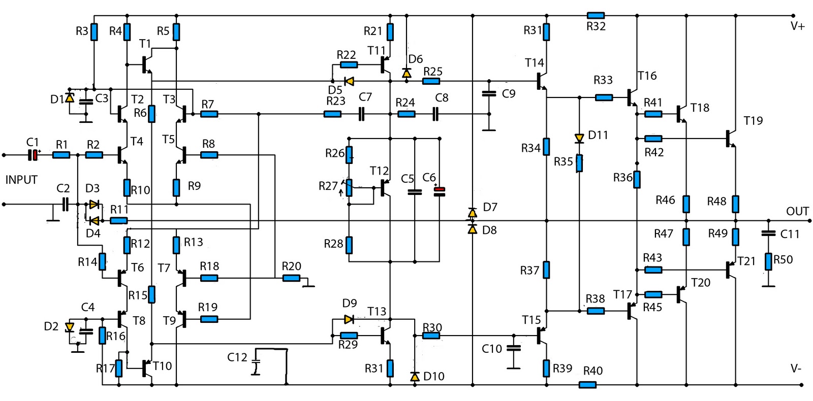
The mono high power amplifier is rated at 1400 W. To create a stereo high power amplifier, which would require a total of 2800 W, the necessary components and PCB must be doubled. The schematic circuit diagram provided is...
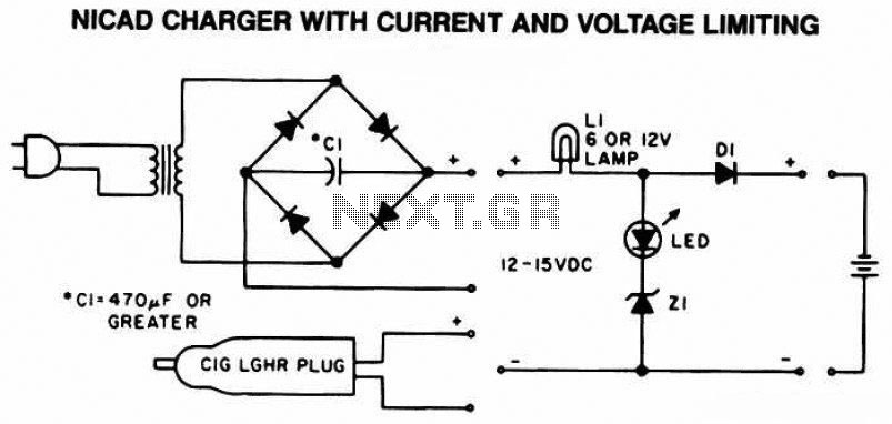
The following diagram is the schematic of a Ni-CAD battery charger circuit, which includes current and voltage limiting features to extend the battery's lifespan. The lamp L1 will illuminate brightly, and the LED will be off when the battery...
Switching regulator subsystems intended for use as DC to DC converters. 3V to 40 Volt DC Converter circuit. The use of switching regulators is becoming more pronounced than that of linear regulators because the size reductions in new equipment...
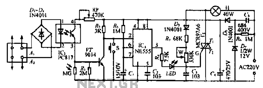
The Ai. A2 series operates with a telephone line, where sound anomalies or off-hook currents activate a light within an arc tube, which in turn triggers a photosensitive MOSFET. This process involves a saturated conduction base voltage that sends...