
Beeper driver with 555
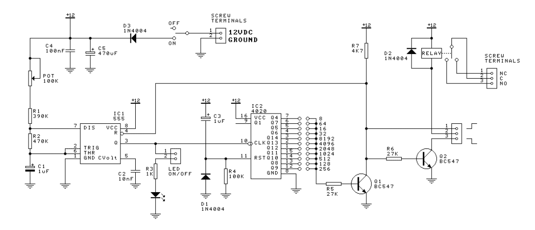
The circuit described utilizes two 555 timer integrated circuits (ICs) configured in astable mode to generate a periodic "beep-beep" sound characteristic of a pager. The first 555 timer (IC1) operates as an oscillator, producing a square wave output at approximately 1 Hz. This output serves as the trigger for the second 555 timer (IC2), which is also configured in astable mode but operates at a higher frequency to generate the audible tone.
IC1's output frequency is determined by the resistor and capacitor values connected to it, particularly R1, R2, and C1. The timing components can be adjusted to change the frequency of the oscillation, effectively controlling how often IC2 is activated. The variable resistor VR1 allows for fine-tuning of this frequency, enabling the user to adjust the rate at which the second IC is turned ON and OFF.
IC2's output frequency, which produces the tone of the final sound, is controlled by its own timing components (R3, R4, and C2). The variable resistor VR2 provides the ability to modify the tone of the output sound, allowing for a range of audible frequencies to be generated. This flexibility is essential for customizing the sound output to meet specific requirements or preferences.
For applications where space or component count is a concern, a piezoelectric buzzer can be used in place of IC2. This substitution simplifies the circuit by eliminating the need for the second 555 timer and its associated components. However, it is important to note that while a piezoelectric buzzer is more compact, it typically produces a quieter sound and lacks the ability to vary tone as effectively as a speaker connected to IC2. Thus, the choice between using a second 555 timer or a piezoelectric buzzer depends on the desired sound characteristics and application requirements.This circuit produces the sound of a beeper like the one in pagers which produces a "beep-beep" sound. Basically the circuit consists of a 555 timer oscillator which is turned ON and OFF periodically. The first IC(left) oscillates at about 1Hz. The second IC is turned ON and OFF by the first IC. The first IC determines how fast the second IC is turned ON/OFF and second IC determines the tone of the final output.
By varying the VR1, the changeover rate can be adjusted. By varying VR2 the tone can be adjusted. If you know something about electronics, you can try replacing the 2nd 555 IC circuit with a piezoelectric buzzer. This saves one IC and associated components but the buzzer cannot give a loud sound as the speaker and also its tone cannot be varied.
🔗 External reference
Related Circuits
In the following astable multivibrator circuit, some sources state that the duty cycle is represented as d = (R1 + R2) / (R1 + 2 * R2), while other sources provide different information. The astable multivibrator circuit is a type...
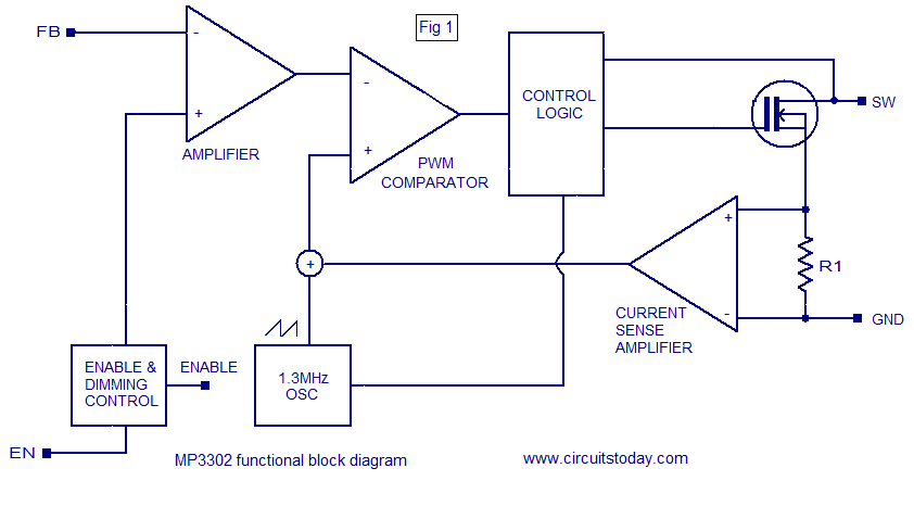
The MP3302 is a boost converter integrated circuit (IC) specifically designed for LED drive applications. It is capable of driving 27 LEDs, arranged as 9 strings of 3 white LEDs in series, powered by a lithium-ion battery. The IC...
This circuit takes standard 0-10V control voltage (for example from analogue light controlling desk) and outputs a standard 1-2 ms RC servo motors control pulse. Power supply: 4-5V DC (same as for RC servo), consumes 15 mA of current....
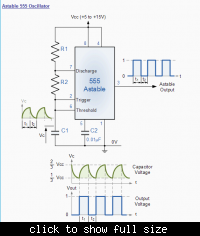
The 555 is configured in the standard astable oscillator circuit designed to give a square wave cycle at a period of around 1 cycle/sec. A potentiometer is included in the design so the period can be set to exactly...
The LM111 comparator can be utilized to design a relay driver with a TTL strobe, which enhances control over the relay driver. The strobe signal can be used to manage the relay operation more effectively. The LM111 is a high-speed...
To simplify the driver circuit, a multiplexer circuit can be utilized as a solution. With this multiplexed BCD decoder, only one BCD is required. A multiplexer (MUX) is an essential component in digital circuits, allowing multiple input signals to be...