
Simple Burglar Alarm circuit
The single-zone burglar alarm circuit is constructed using a combination of resistors, capacitors, diodes, and operational amplifiers to create a reliable and efficient security system. The circuit typically includes a power supply that provides the necessary voltage for operation, usually in the range of 9V to 12V DC. The input devices, such as magnetic reed contacts or PIR sensors, are connected to the circuit in a normally-closed configuration. This ensures that any unauthorized opening of doors or windows will trigger the alarm.
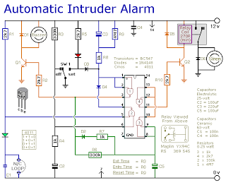
The control switch SW1 is a crucial component that allows users to set or deactivate the alarm. When SW1 is moved to the "set" position, it engages the timing circuit, which is responsible for the exit delay. The red LED serves as an indicator that the alarm is armed, while the green LED indicates that the system is ready for operation.
The timing mechanism is typically implemented using a resistor-capacitor (RC) network, where R3, R6, and R9 are strategically chosen to define the timing intervals. The use of a relay in the circuit allows for the control of the siren and other output devices, ensuring that the alarm can sound loudly enough to deter intruders.
The design also incorporates a feedback mechanism that monitors the state of the input devices. If the circuit detects that a door or window has been opened after the exit delay has expired, the buzzer activates, providing a secondary alert before the siren is engaged.
The siren's cut-off feature is an important safety measure, preventing continuous alarm sound in the event of a false trigger or if the system is inadvertently left in an alarm state. The ability to adjust the timing of the exit, entry, and siren cut-off enhances the flexibility of the system, allowing it to be tailored to different environments and user preferences.
Overall, this burglar alarm circuit provides a simple yet effective solution for securing a single zone, with the potential for customization to accommodate various triggering devices and timing requirements.This is a simple single-zone burglar alarm circuit. Its features include automatic Exit and Entry delays and a timed Bell/Siren Cut-Off. It`s designed to be used with the usual types of normally-closed input devices such as - magnetic reed contacts - micro switches - foil tape - and PIRs. But it can be Easily Modified to accept normally-open trigg ering devices - such as pressure mats. It`s easy to use. First check that the building is secure and that the green LED is lit. Then move SW1 to the "set" position. The red LED will light. You now have about 30 seconds to leave the building. When you return and open the door - the Buzzer will sound. You then have about 30 seconds to move SW1 to the "off" position. If you fail to do so - the relay will energize and the Siren will sound. While at least one of the switches in the normally-closed loop remains open - the Siren will continue to sound. However, about 15-minutes after the loop has been restored - the relay will de-energize - the Siren will Cut-Off - and the alarm will Reset.
Of course, you can turn the Siren off at any time by moving SW1 to the "off" position. Because of manufacturing tolerances - the precise length of any delay depends on the characteristics of the actual components you`ve used in your circuit. But by altering the values of R3, R6 & R9 you can adjust the Exit, Entry and Bell Cut-Off times to suit your requirements.
Increasing the values increases the time - and vice-versa. 🔗 External reference
Related Circuits

The Tesla Coil will utilize a high voltage (HV) power source that outputs 9 kV at approximately 30 mA. The construction of the Tesla coil includes six glass bottles, table salt, oil, and aluminum foil for the capacitors. The...

The thermostat electric circuit operates as depicted in the figure. It has three settings: off, low power (Lo), and high power (Peru HL). When the DIP switch SA is set to the Lo position, 220V AC is directed through...

This circuit converts a sine wave into a square wave. It consists of a single 2-input NAND Schmitt trigger configured as an inverter, with an adjustable trigger level at its input. As the input voltage exceeds the gate's trigger...

The car radio application utilizes a Class AB Audio Power Amplifier, typically featuring the TDA7360 IC. This amplifier provides 22W output in either bridge or stereo configuration and includes several beneficial features such as a minimal requirement for external...

This project involves a 12V LED lamp circuit that is notably simple. The circuit comprises five resistors and fifteen super bright white 5mm LEDs, which are readily available at low prices. It is compatible with any type of 12-volt...

IC1-c functions as a non-inverting comparator, while IC1-a operates as an inverting comparator. Potentiometer R1 and fixed resistors R2 and R3 create a voltage divider chain that provides slightly different voltages to the two comparators. These voltages establish the...