
555 low power timing circuit diagram
The 555 timer IC is widely utilized in various applications due to its versatility and ease of use. In a low power timing circuit configuration, the 555 timer can function in both astable and monostable modes, allowing it to generate precise timing intervals or oscillations.
In the astable mode, the circuit continuously oscillates between high and low states, producing a square wave output. This configuration requires two resistors (R1 and R2) and a capacitor (C1) connected to the threshold and discharge pins of the 555 timer. The frequency of oscillation and duty cycle can be calculated using the formulas:
Frequency (f) = 1.44 / ((R1 + 2 * R2) * C1)
Duty Cycle (%) = (R2 / (R1 + 2 * R2)) * 100
In monostable mode, the 555 timer generates a single pulse when triggered. The duration of the pulse is determined by a resistor (R) and a capacitor (C) connected to the timing pins. The pulse width can be calculated as:
Pulse Width (T) = 1.1 * R * C
To minimize power consumption, low value resistors and capacitors can be selected, and the timer can be powered using low voltage sources. Additionally, the use of bypass capacitors near the power supply pins can help reduce noise and improve circuit stability.
The application of the 555 low power timing circuit can be found in timer applications, pulse generation, LED flashing circuits, and many other timing-related tasks. Proper layout and grounding techniques should be employed to ensure optimal performance and minimize interference.555 low power timing circuit diagram The diagram is from the tech information of chinaicmart. IF for more detailed infomation of the circuit diagram.. 🔗 External reference
Related Circuits
This chapter contains circuit diagrams for several power supplies for pulsed solid-state lasers. These include units suitable for driving the popular Hughes ruby and YAG rangefinder laser assemblies, one utilizing the flash from a disposable pocket camera, and a...
The 7915 (at least the "made in Morocco" I used) needs a small load (some mA) to work correctly. If you get funny voltages (-18.4V or so), put a resistor from the 7915 output to ground (2k2 works good)....
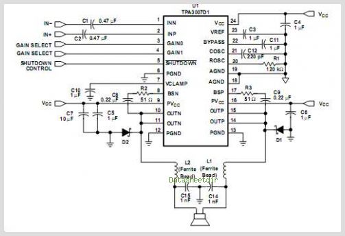
The TPA3112D1 is a 25-W efficient Class-D audio power amplifier designed for driving a bridge-tied speaker. It incorporates advanced EMI suppression technology, allowing the use of cost-effective ferrite bead filters at the outputs while complying with EMC requirements. The...
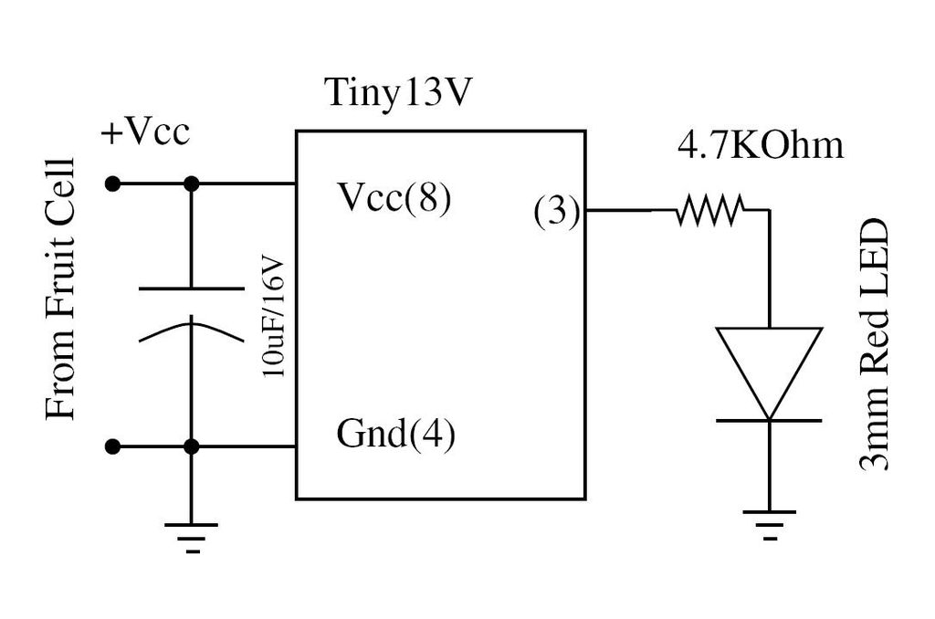
Wire the circuit diagram shown here on a breadboard. The choice of V type of AVR is important. For example, Tiny13V is very appropriate for such an application. To successfully implement the circuit diagram on a breadboard, several considerations must...
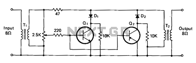
T1 and T2 are 600 to 8-ohm transformers (any transistor radio output transformers with 500 to 4-ohm impedance may be used). Q1 is a 2N2222 NPN transistor, and Q2 is a 2N2907 PNP transistor. D1 and D2 are 1N270...
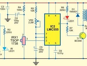
This type of infrared proximity circuit is commonly utilized as an electric switch where physical contact is undesirable for hygiene reasons. For instance, infrared proximity sensors are frequently found in public drinking fountains and washrooms. The straightforward circuit described...
Warning: include(partials/cookie-banner.php): Failed to open stream: Permission denied in /var/www/html/nextgr/view-circuit.php on line 713
Warning: include(): Failed opening 'partials/cookie-banner.php' for inclusion (include_path='.:/usr/share/php') in /var/www/html/nextgr/view-circuit.php on line 713