
Audio-powered noise clipper
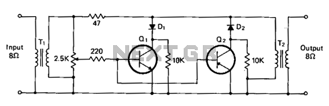
The circuit employs two transformers, T1 and T2, designed to match a high-impedance audio source to a lower impedance load. These transformers facilitate the conversion of audio signals, ensuring efficient power transfer and minimizing signal loss. The choice of transformers with an impedance ratio of 600 to 8 ohms allows for compatibility with various audio equipment, while the option to use transistor radio output transformers with 500 to 4 ohms offers flexibility in circuit design.
Transistors Q1 and Q2 serve as the primary active components responsible for signal processing. The 2N2222 NPN transistor (Q1) and the 2N2907 PNP transistor (Q2) are commonly used in audio applications due to their reliability and performance characteristics. In this configuration, Q1 is responsible for clipping the positive peaks of the audio signal, while Q2 handles the negative peaks. This clipping action is critical for preventing distortion and maintaining audio fidelity at higher signal levels.
The inclusion of diodes D1 and D2, specifically 1N270 signal diodes, plays a crucial role in isolating the clipping circuits. The diodes allow for unidirectional flow of current, ensuring that each transistor only engages in clipping its respective half of the audio waveform. This isolation not only protects the transistors from potential damage due to reverse current but also enhances the overall performance of the circuit by maintaining a clean separation between the positive and negative clipping processes.
The circuit also features a 2.5 kΩ potentiometer, which is used to set the threshold level for clipping. By adjusting this potentiometer, the user can establish the desired audio operating level, allowing for customization based on the specific requirements of the audio signal being processed. Once set, the potentiometer typically requires little to no further adjustment, providing a stable and reliable operation throughout the audio processing task.
Overall, this circuit design effectively combines transformers, transistors, and diodes to create a robust audio signal processing solution, capable of managing clipping while ensuring high-quality audio output.Tl and T2 are 600 to 8 ohm transformers (any transistor radio output transformers with 500 to 4 ohm impedance may be used). Ql is a 2N2222 npn transistor, and Q2 is a 2N2907 pnp transistor. Dl and D2 1N270 signal diodes (HEP 134 or 135). Two transistors, powered by the audio power contained within the signal, will clip signal peaks which exceed the threshold established by the 2.5 potentiometer.
The diodes isolate the positive and negative clipping circuits represented by the npn and pnp transistors, respectively. A desired audio operating level can be established and the potentiometer needs little or no further adjustment. 🔗 External reference
Related Circuits
The circuit described is a simple sound level meter, also known as a VU meter, which helps monitor sound levels to prevent hearing loss caused by loud music. It is a passive type of meter, requiring no separate power...
This circuit is effective for testing audio circuits using broadband noise. It employs three inexpensive C-MOS integrated circuits (ICs) that produce a series of output pulses with randomly varying widths. The audio noise generator is designed to drive earphones...

This circuit is designed to indicate, via a flashing LED, when room noise exceeds a predetermined threshold, selectable from three fixed levels: 50 dB, 70 dB, and 85 dB. The circuit utilizes two operational amplifiers to amplify the sound...
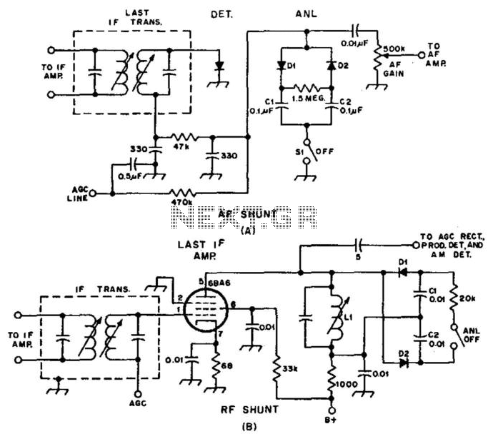
Examples of RF and audio ANL circuits. Positive and negative clipping occurs in both circuits. The circuit is self-adjusting. This noise limiter operates at the IF output. Adequate gain is needed at the IF frequency so that several volts...
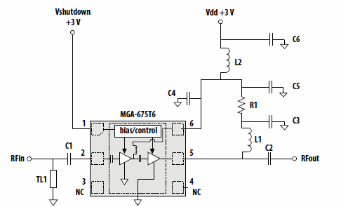
This application note discusses the use of Avago Technologies' MGA-675T6 for 5-6 GHz applications. The MGA-675T6 is internally integrated with shutdown and biasing circuitry, which simplifies the external circuitry. The shutdown feature allows the low noise amplifier (LNA) to...
This circuit is designed to indicate when room noise exceeds a predetermined threshold, utilizing a flashing LED to signal this condition. Three fixed noise levels are selectable: 50 dB, 70 dB, and 85 dB. The circuit employs two operational...