
touch free timer switch circuit
The infrared proximity circuit operates on the principle of detecting the reflection of modulated infrared light. The astable multivibrator configuration of the LMC555 timer generates a continuous square wave signal, which is transmitted via the infrared LED. The frequency of 38 kHz is chosen because it is typically less susceptible to interference from ambient light sources, making it ideal for proximity detection applications.
In the receiver section, the TSOP1738 module demodulates the incoming infrared signal. This module is designed to recognize the specific frequency of the transmitted signal, thus ensuring that only relevant signals trigger the output. The output of the TSOP1738 is fed into the trigger pin of the second LMC555 timer, which is configured in monostable mode. The duration for which the output remains high is adjustable, allowing for flexibility in the circuit's response time.
Transistor T1 acts as a switch to control the relay RL1, which can handle higher load currents, allowing the circuit to control various devices such as lights or pumps without direct contact. The design emphasizes safety and hygiene, making it suitable for public installations. Proper assembly and enclosure design are crucial for the performance and reliability of the circuit, particularly in environments where it will be exposed to varying light conditions and potential physical obstructions.This type of infrared proximity circuit is widely used as an electric switch where physical contact is not desired for hygiene purpose. For example, we commonly see use of infrared proximity sensors on public drinking fountains and in public washrooms.
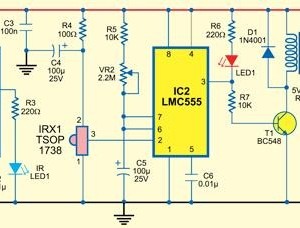
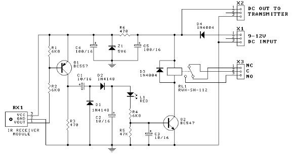
The simple circuit presented here can be operated by moving your hand in front of it. This is ac hieved by detecting the infrared light reflected by your hand onto a receiver device. Fig. 1 shows the circuit of the touch-free timer switch. It has two sections: transmitter and receiver. The IR transmitter is built around timer LMC555 (IC1), which is wired as an astable multivibrator. The multivibrator produces 38kHz pulses (at low duty cycle) that drive an infrared LED (LED1). This frequency can be tuned using a 10-kilo-ohm preset (VR1). A 220-ohm series resistor (R3) ensures that the current consumption of the IR transmitter is not out of arrangement. The receiver section is built around IR receiver module TSOP1738 (IRX1), timer LMC555 (IC2) and a few discrete components.
The TSOP1738 is an integrated miniaturised receiver for infrared remote control systems. Everything required for IR signal processing, including the PIN diode and preamplifier, are assembled on a lead frame and the epoxy package is designed as an IR filter. When a short IR burst is received by IRX1 (as you wave your hand in front of the switch), the demodulated pulses are fed to the trigger input (pin 2) of the second LMC555 (IC2).
This, in turn, triggers the monostable wired around IC2 and its output pin 3 goes high for a period determined by the 2. 2-mega-ohm potentiometer and capacitor C5. This turns off the standby indicator (LED1) and transistor T1 conducts to drive the 5V relay (RL1). LED1 enables you to locate the switch in the dark. AC mains supply to the load to be switched-on is routed through the pole and normally-opened contacts of RL1 as shown in the diagram.
The circuit works off regulated 5V DC. Fig. 2 shows the pin configurations of TSOP1738, IR LED1 and transistor BC547. Assemble the circuit on a general-purpose PCB and enclose in a small plastic cabinet. Fit IR LED1 with a reflecting hood at a recessed position on the front panel of the enclosure. The dome-shaped face of the TSOP1738 should stick out from the front panel. Fit the time-control potentiometer (VR2) in an appropriate position. Finally, fit the standby indicator LED1 inside a suitable LED holder such that it slightly protrudes from the front panel. To prevent unwanted reflection of the IR beam, the finished unit should be mounted such that it does not face a nearby wall.
Using high-precision linear potentiometer VR2 and capacitor C5 (100 µF), the time length can be set from nearly 1 second to 120 seconds. Attach a small paper dial on the front panel of the enclosure and mark various positions of the control knob of VR2 as shown in Fig.
3. The accuracy of the timer depends mainly upon the quality (and value) of timing capacitor C5. In practice, most electrolytic capacitors are rated on the basis of minimum guaranteed value and the real value may be higher. 🔗 External reference
Related Circuits
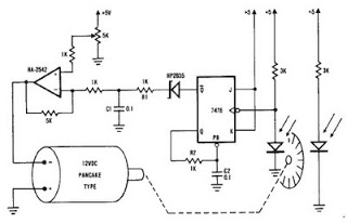
A simple encoder circuit for a DC motor can be constructed using the provided circuit diagram. The system includes the HA-2542 operational amplifier, a small 12 V DC motor, and a position encoder. During operation, the encoder generates a...
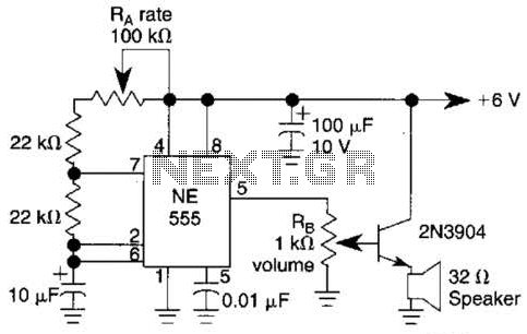
Ra sets the rate while RH sets the volume of clocks in the speaker. The 555 is configured as a low frequency oscillator. The circuit is powered by a 6 V battery. The circuit utilizes a 555 timer IC configured...
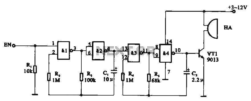
Tone generator circuit. The tone generator circuit utilizes a quad 2-input NAND gate integrated circuit, specifically the CD4011. NAND gates 1 and 2, along with NAND gates 3 and 4, form two gating multivibrator oscillators. The oscillation period of...
This door minder electronic project is based on a 555 timer circuit and utilizes an infrared (IR) beam to monitor doorways, passageways, or any other designated area. When the IR beam is interrupted, a relay is activated, which can...
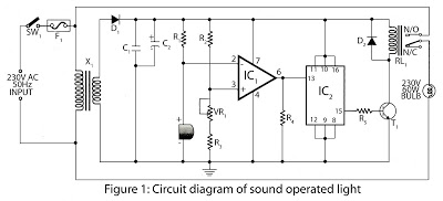
This is a hobby circuit designed for electronics enthusiasts that can turn on and off devices such as lights, fans, and radios in response to the sound of a clap. The sound is detected by a small microphone, which...
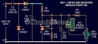
This document presents an infrared remote control tester circuit that can be constructed at a low cost. The circuit is built around the infrared receiver module TSOP1738. The state of the remote control can be observed through the sound...
Warning: include(partials/cookie-banner.php): Failed to open stream: Permission denied in /var/www/html/nextgr/view-circuit.php on line 713
Warning: include(): Failed opening 'partials/cookie-banner.php' for inclusion (include_path='.:/usr/share/php') in /var/www/html/nextgr/view-circuit.php on line 713