
555 make use of digital amplifier circuit diagram
The Class-D amplifier circuit described is based on the operation of the 555 timer IC, which functions as a versatile multivibrator capable of generating PWM signals. The circuit is designed for audio amplification, taking advantage of the high efficiency and compact nature of Class-D amplification technology.
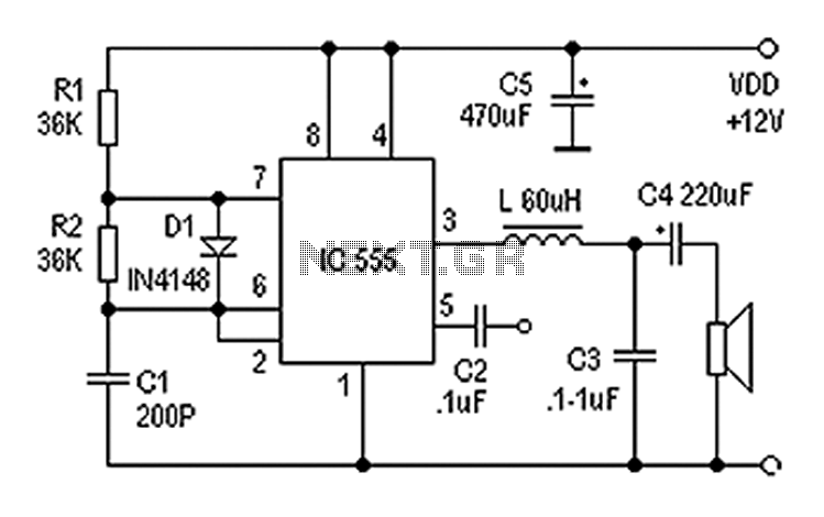
In this configuration, the input audio signal is connected to pin 5 of the 555 timer. The resistors R1 and R2, along with capacitor C1, are selected to set the frequency of the PWM output to 100 kHz with a 50% duty cycle. This frequency is optimal for audio applications, allowing for effective modulation of the audio signal without significant distortion.
The output from pin 3 of the 555 timer provides a PWM signal that varies in width according to the amplitude of the input audio signal. This relationship is crucial for maintaining audio fidelity, as the width of the pulses directly correlates to the amplitude of the original audio waveform.
To drive a speaker, the PWM signal is passed through an inductor L and capacitor C3, which serve as a low-pass filter. This filtering process smooths the PWM signal, converting it back into an analog audio signal suitable for driving a speaker. The inductor helps to block high-frequency components, while the capacitor assists in smoothing the output, ensuring that the final signal is clean and free of unwanted artifacts.
Overall, this Class-D amplifier circuit using the 555 timer is an efficient and effective solution for audio amplification, providing a compact design with high performance for various listening applications.Also known as digital amplifier Class-D amplifier with small size, high efficiency characteristics. Here are a circuit made easy with 555 Class D amplifier. It is the use of ci rcuit 555 constitute a controllable multivibrator, an audio signal input to the control terminal to obtain a pulse width modulated signal (as shown), to meet the basic requirements for general listening. By the IC 555 and R1, R2, C1 and other components 100KHz controlled multivibrator 50% duty cycle, control the input audio signal terminal 5 feet, 3 feet will get the pulse width of the input signal amplitude is proportional to the pulse signal by L, C3 to answer the call, push the speaker after filtering.
Related Circuits
The task involved testing the capacitive properties of food by connecting various edibles to an Arduino. This project, known as BeetBox, was developed by Scott Garner, a student at NYU-ITP, who designed an innovative musical instrument that uses beets...
The problem with class-B amplifier design is that we start with an output stage in two halves, each with a non-linear response, which we then add together to try to give a linear response, i.e. so that a graph...
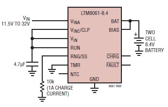
A simple and efficient lithium battery charger and monitoring system can be designed using the LTM8061 integrated circuit from Linear Technology. The LTM8061 is a high-efficiency 32V, 2A module standalone lithium battery charger optimized for one- and two-cell packs,...
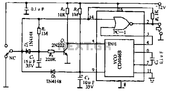
The figure illustrates a circuit involving dark tomb electric locks, specifically the fti: al: 4046B and XOR gate as the primary control mechanism. It emits pulses and utilizes silicon for successive pulse generation. The circuit operates with a normal...
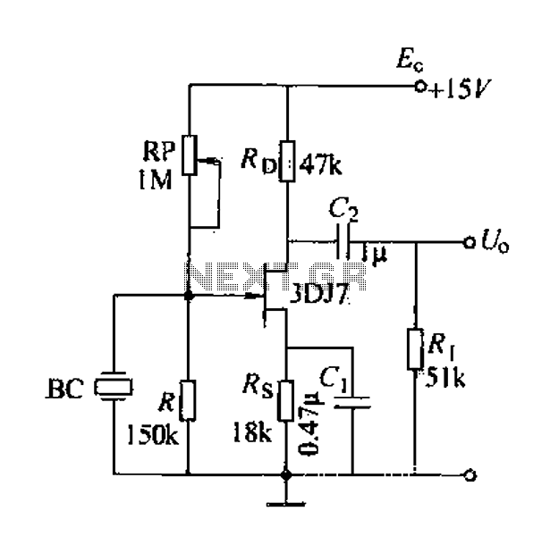
A field effect transistor (FET) voice amplifier has a low input impedance, approximately 1 kΩ, requiring the signal source to provide a constant current signal for operation. Unlike bipolar transistors, FETs are voltage-controlled devices that draw minimal current at...
The 74AC240 stepper driver works by alternately enabling each half of the buffer. Only one half can be enabled at a time. Let’s assume that the top half of the driver is enabled. U1A & U1B along with R8,...