
555 Oscillator With 50% Duty Cycle

The 555 timer IC is a versatile component commonly used in various timing applications, including astable multivibrator configurations to generate square wave signals. To create a 50% duty cycle, it is essential to ensure that the time spent in the high state is equal to the time spent in the low state during each cycle.
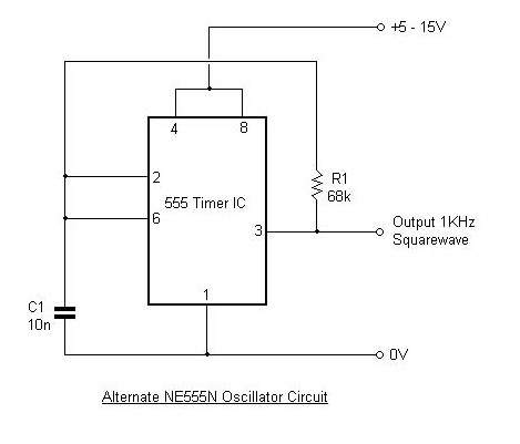
In a typical astable configuration, the 555 timer operates with two resistors (R1 and R2) and a capacitor (C1). The duty cycle can be adjusted by varying the values of these resistors. However, to achieve precise control over the duty cycle, the use of diodes can be advantageous. By integrating two diodes into the circuit, one diode can be placed in the charging path (connected to the capacitor) and another in the discharging path. This arrangement allows for different resistance values during charging and discharging, enabling a balanced duty cycle.
In the absence of diodes, the duty cycle can still be approximated at 50% by selecting appropriate resistor values. For a 50% duty cycle, the relationship between the resistors and the capacitor must be carefully calculated to ensure that the time constant for charging (T1) equals the time constant for discharging (T2). The formula for the duty cycle in this configuration can be expressed as:
Duty Cycle (%) = (T1 / (T1 + T2)) * 100
Where T1 = 0.693 * (R1 + R2) * C1 and T2 = 0.693 * R2 * C1.
To summarize, achieving a 50% duty cycle using a 555 timer IC can be effectively accomplished through the use of diodes for enhanced control or by careful selection of resistor values in a diode-free configuration. This flexibility allows designers to tailor the circuit to specific application requirements while maintaining the desired output waveform characteristics.To generate 50% active factor (duty cycle) using 555 IC, we can use two diodes to separate the charging and the discharging path. With no diodes, we can also.. 🔗 External reference
Related Circuits
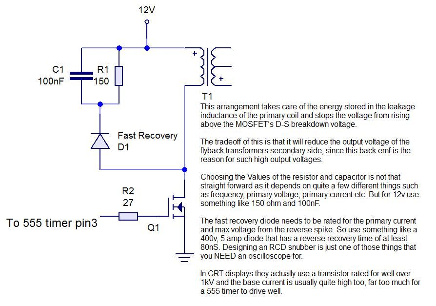
This instructable demonstrates the process of creating an audio-modulated plasma speaker using a flyback transformer salvaged from an old CRT display. The audio-modulated plasma speaker operates by utilizing a high-voltage output from a flyback transformer to create a plasma arc...
The NCP5810D is a dual-output DC/DC converter capable of generating both positive and negative voltages. This device is optimized for powering modules such as AMOLED display drivers, where high output voltage accuracy, regulation, signal integrity, and compact design are...
The fishing circuit, as illustrated in figure 11-6, comprises a timing circuit and an audio circuit. The components 555, RP1, and C1 form the single-shot circuit, with the defined time calculated as td = 1.1RP1C1. The maximum defined time...

This circuit is designed as a pocket-sized, high-performance audio oscillator. It can operate using a battery-powered version, which is feasible at a very low cost by utilizing a single quad op-amp to provide the entire active circuitry. The design...
The object is to get the cell voltage high enough for the sulphate to dissolve without boiling or melting the battery. This is achieved by applying higher voltage for shorter periods and let the battery rest for a while....
This article outlines the design and applications of the NE555 timer. The content is straightforward and informative, providing valuable insights into various components associated with the NE555. Readers can find and purchase these components through the article. It discusses...