
555 precision temperature sensor with temperature frequency converting circuit diagram
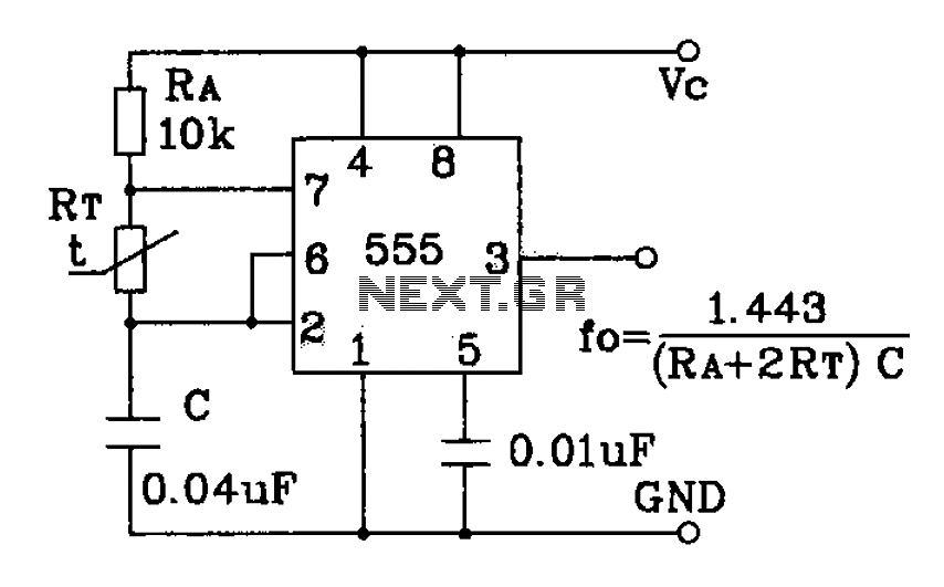
The 555 precision temperature sensor operates by converting temperature variations into frequency signals. This circuit typically utilizes a 555 timer IC configured in astable mode to generate a pulse-width modulation (PWM) signal whose frequency is directly proportional to the temperature being measured.
In this configuration, the temperature sensor (often a thermistor or an integrated temperature sensing component) is connected to the input of the 555 timer. As the temperature changes, the resistance of the sensor alters, which in turn modifies the charge and discharge times of the timing capacitor connected to the 555 timer. This results in a frequency output that varies with temperature.
The circuit may include additional components such as resistors and capacitors to fine-tune the frequency response and to stabilize the operation of the 555 timer. The output frequency can be measured using a frequency counter or microcontroller, allowing for precise temperature monitoring and control applications.
This design is particularly useful in applications that require temperature measurement in real-time, such as in HVAC systems, environmental monitoring, and industrial processes where temperature regulation is critical. The simplicity and reliability of the 555 timer make it an excellent choice for integrating temperature sensing capabilities into various electronic systems.555 precision temperature sensor with temperature frequency converting circuit diagram consisting of:
Related Circuits

This voltage-controlled oscillator circuit is compact and exhibits good linearity. The precision can be better than 0.01% if properly constructed. The circuit provides three different output waveforms: square, triangle, and sawtooth, which are essential for music synthesizers and measurement...
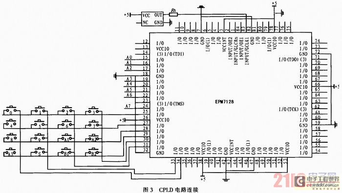
The system utilizes a modular design featuring the AT89S52 microcontroller and CPLD as the central processing unit (CPU) for overall system coordination. Initially, it establishes a cycle of systematic pulse signals through a 4G-4 key set module, allowing for...
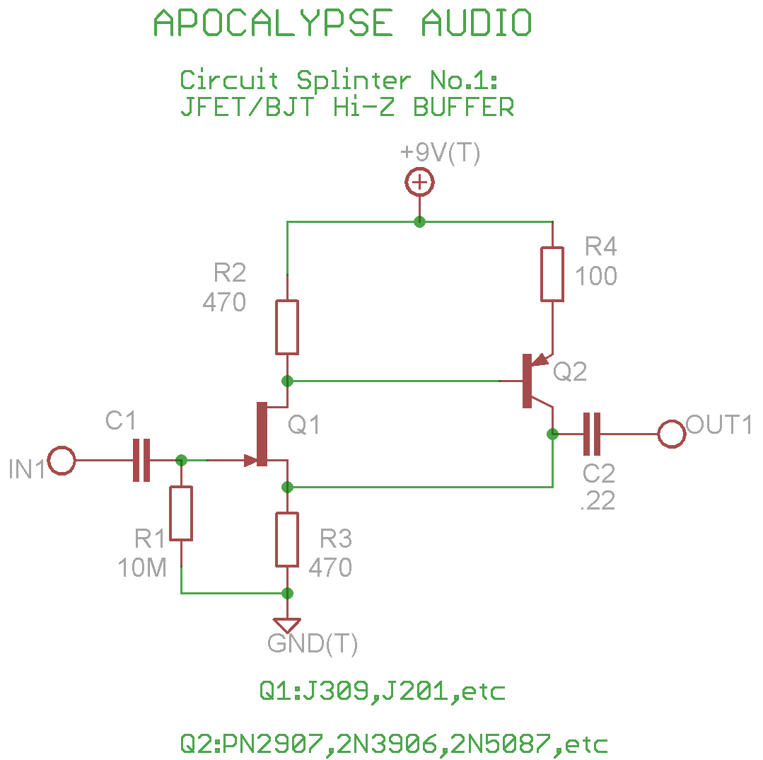
This is a common circuit often found in various resources, yet it appears to be less prevalent in stompbox applications. The circuit utilizes an NPN JFET DC coupled with a PNP BJT. The FET provides a significantly higher input...
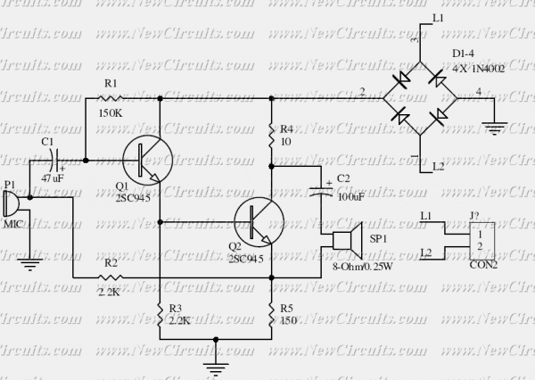
This is the basis of electronics telephone sets. You can use it to replace the talking circuit of an old telephone set with new design, better noise rejection and reliability one. Also you can use it to build a...
The use of a quarter-wave parallel-wire line as a tuning unit has been discussed in the chapter on Short-Lines, where it was pointed out that these circuits have comparatively high Q even at higher frequencies. Their significant length (approximately...
DTMF-based Robo Car design using the 8051 microcontroller project. This project demonstrates a method to control a domestic system using the DTMF tone generated by a telephone instrument when the user presses the keypad buttons of a mobile phone...
Warning: include(partials/cookie-banner.php): Failed to open stream: Permission denied in /var/www/html/nextgr/view-circuit.php on line 713
Warning: include(): Failed opening 'partials/cookie-banner.php' for inclusion (include_path='.:/usr/share/php') in /var/www/html/nextgr/view-circuit.php on line 713