
Electronics Telephone Talking Circuit
The electronic telephone set circuit serves as a fundamental component in modern telecommunications, allowing for the replacement of outdated talking circuits in traditional telephone sets. This updated design emphasizes improved noise rejection and enhanced reliability, addressing common issues found in older models.
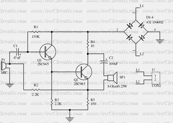
The circuit typically includes a microphone for sound input, an amplifier to boost the audio signal, and a speaker for sound output. The microphone converts sound waves into electrical signals, which are then amplified to ensure clarity and volume when transmitted through the telephone line. The output from the amplifier is sent to a speaker, which converts the electrical signals back into audible sound.
Additionally, the circuit can be designed to function without a dial mechanism, allowing for simpler operation where users can answer incoming calls without the need for dialing. This feature is particularly useful in environments where ease of use is paramount, such as in emergency services or for individuals with mobility challenges.
Furthermore, careful consideration should be given to the choice of components to maximize noise rejection. This may involve using high-quality capacitors and resistors, as well as implementing shielding techniques to minimize electromagnetic interference. The layout of the circuit board is also crucial; proper placement of components can help reduce parasitic capacitance and inductance, which can adversely affect signal integrity.
In summary, this electronic telephone set circuit design not only modernizes traditional telephone systems but also enhances user experience through improved performance and functionality.This is the basis of electronics telephone sets. You can use it to replace the talking circuit of an old telephone set with new design, better noise rejection and reliability one. Also you can use it to build a telephone set without dial circuit to answer a call. 🔗 External reference
Related Circuits
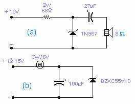
These two circuits are interesting from an academic point of view. Their practical implementation is rather critical and it is not easy to get steady operation. Circuit (a) requires a "cooked" zener: connect it first to a constant current...
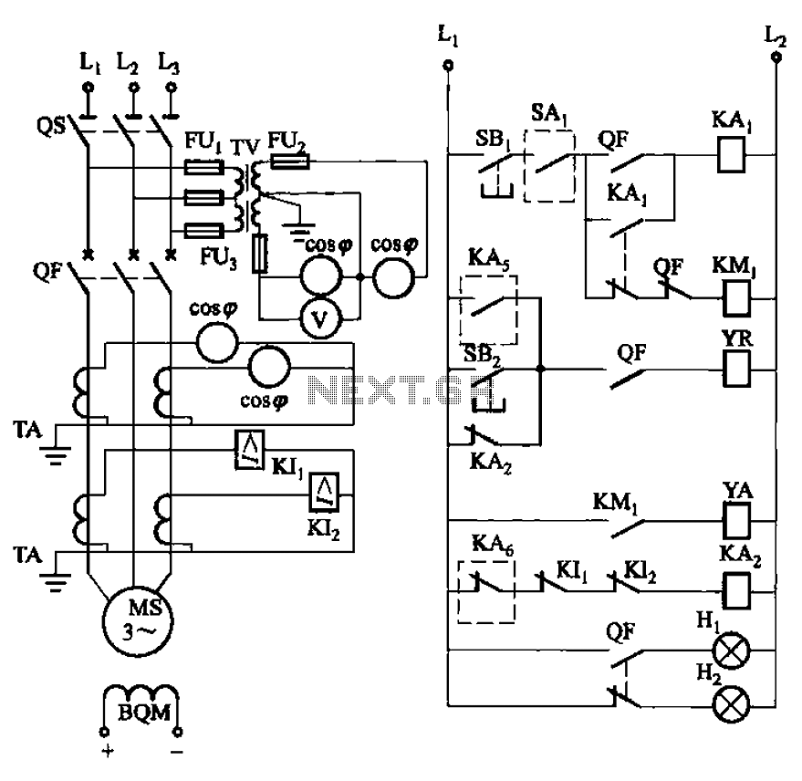
The circuit depicted in Figure 3-186 includes an isolation switch, QF vacuum circuit breakers, YR line for the circuit breaker coil, and YA for the circuit breaker closing coil. Additionally, there is a dashed box representing the excitation device...
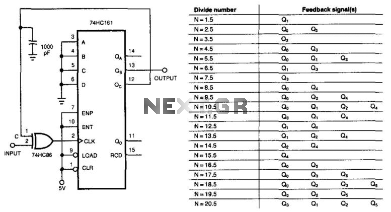
This circuit divides the input signal by +1/2 instead of dividing by an integer. With the feedback connections as illustrated in the figure, the circuit effectively divides by 3.5. Point C ultimately determines when the input triggers the 74HC161...

This inverter circuit is designed to power electric razors, stroboscopes, flash tubes, and small fluorescent lamps using a 12-volt car battery. Unlike conventional feedback oscillator inverters, this design features a separate oscillator from the output stage, allowing for easy...

This document illustrates the configuration of the high-precision, high-impedance OPA2111 amplifier. The total voltage circuit is designed for a magnification of Av = 10 (1 + 2R2 / R1), achieving a total gain of 1000 times. A gain stage...
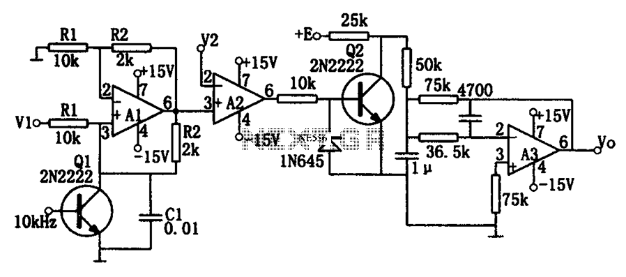
As illustrated in the dividing circuit diagram, A1 consists of a voltage-controlled current source, A2 functions as a voltage comparator, and A3 is configured as an active low-pass filter. When the time constant R1C1 is equal to the clock...
Warning: include(partials/cookie-banner.php): Failed to open stream: Permission denied in /var/www/html/nextgr/view-circuit.php on line 713
Warning: include(): Failed opening 'partials/cookie-banner.php' for inclusion (include_path='.:/usr/share/php') in /var/www/html/nextgr/view-circuit.php on line 713