
Simple FM Modulator Design
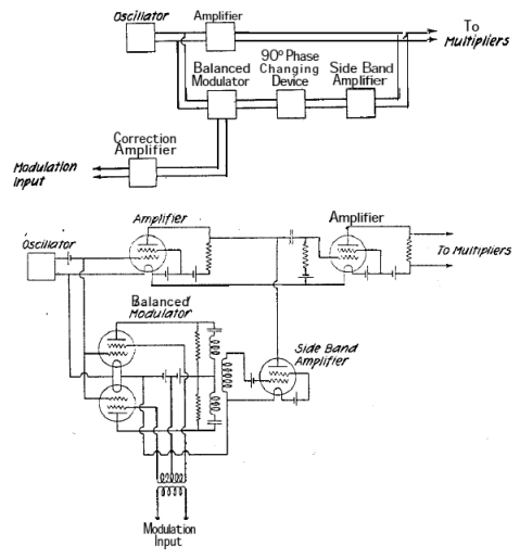
The design of an FM transmission system involves several key components, including oscillators, modulators, amplifiers, and antennas. The oscillators, which have already been constructed, are crucial as they generate the carrier signals at specific frequencies within the FM band, typically ranging from 88 MHz to 108 MHz.
To achieve multi-frequency transmission, a frequency synthesizer may be employed, allowing for precise tuning and stability across the desired frequency range. This can be accomplished using phase-locked loops (PLLs) or direct digital synthesis (DDS) techniques, which provide flexibility in frequency selection and modulation.
The modulation stage is essential for encoding the audio or data signal onto the carrier wave. This is typically achieved using a voltage-controlled oscillator (VCO) that varies its frequency based on the amplitude of the input audio signal, effectively creating frequency modulation. The modulated signal is then amplified using RF amplifiers to ensure adequate power for transmission.
The final stage involves the antenna, which must be designed to efficiently radiate the modulated signal into the surrounding environment. The choice of antenna type (e.g., dipole, monopole, or loop) will depend on the desired range and coverage area of the transmission.
Careful consideration must also be given to compliance with regulatory standards governing FM transmissions to avoid interference with other services and ensure proper licensing. Power levels, frequency stability, and bandwidth must all adhere to the relevant guidelines to maintain operational integrity and legality.
Overall, the successful implementation of an FM transmission system requires meticulous design and integration of these components to achieve reliable and high-quality signal transmission.Hello, I want to build a system that can transmit in the FM band. I have already built my oscillators because I want to transmit at more than one.. 🔗 External reference
Related Circuits
The first example utilizes a standard op-amp oscillator circuit to produce a triangular waveform, which is then level-shifted and supplied to a comparator (e.g., LM339) to generate a PWM waveform. It is common for users to prefer using two...
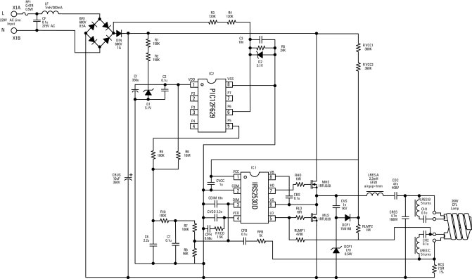
Electronic ballasts for dimming fluorescent lamps require a control interface for the user to set the desired lamp brightness level. Existing interface circuits include a 1-to-10 Vdc interface, a digitally-addressable lighting interface (DALI), triac-based wall dimmers, three-way lamp sockets,...
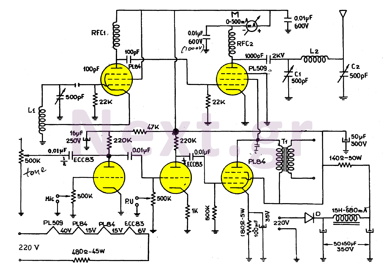
The simplicity of this transmitter, combined with its high performance, makes it particularly interesting. It has an output power of approximately 30 W, and under normal conditions, with the appropriate antenna and handling, it can achieve a range of...
A simple pulse modulator circuit can be constructed using a 555 integrated circuit (IC). The 555 chip features a special modulator input located at pin 5. Below is the schematic diagram of the circuit. The pulse modulator circuit utilizing the...
This simple circuit helps detect RF radiation leaking from transmitters, improper joints, broken cables, or equipment with inadequate RF shielding. This circuit is designed to identify and measure radio frequency (RF) radiation emissions, which can indicate issues such as faulty...

This document outlines the construction of a simple joule thief circuit. A joule thief is a versatile device, particularly useful for powering LED lights from low-voltage power supplies. It is capable of extracting energy from nearly depleted batteries, making...
Warning: include(partials/cookie-banner.php): Failed to open stream: Permission denied in /var/www/html/nextgr/view-circuit.php on line 713
Warning: include(): Failed opening 'partials/cookie-banner.php' for inclusion (include_path='.:/usr/share/php') in /var/www/html/nextgr/view-circuit.php on line 713