
Fluid lever sensor circuit design using ac signal
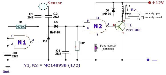
The fluid level sensor circuit leverages an AC sensing mechanism to effectively mitigate the risk of electrolytic corrosion, a common issue in liquid detection systems. The AC signal is first rectified, converting it to a DC voltage suitable for driving the T1 transistor. This transistor acts as a switch, controlling the current flow to a 12-volt relay. The relay's primary function is to engage or disengage connected devices based on the fluid level detected by the sensor.
The sensitivity of the sensor is adjustable through the R2 resistor. By replacing R2 with a variable resistor, users can fine-tune the circuit's response to different fluid levels, allowing for greater flexibility in various applications. This feature is particularly important in environments where fluid characteristics may vary, requiring precise detection thresholds.
The MC104093B component, a P-channel quad 2-input NAND Schmitt trigger, enhances the circuit's reliability by providing noise immunity and ensuring stable switching behavior. Its pin-to-pin compatibility with the CD4093 allows for easy integration into existing designs. Proper handling of unused inputs and outputs is critical; unused inputs should be connected to a defined voltage level (ground or +12 volts) to prevent floating states that could lead to unpredictable behavior. Unused outputs must be left open to maintain the integrity of the circuit.
Overall, this fluid level sensor circuit presents a robust solution for fluid detection, combining effective corrosion prevention with adjustable sensitivity and reliable signal processing capabilities.This fluid level sensor circuit is designed for using an ac sensing signal to eliminate electrolytic corrosion on the probes. The ac signal rectified is used to drive T1 transistor that drives a 12 volt relay, that can activate or stop some device.
R2 resistor is used to modify the sensor sensitivity and can be replaced with a small variable res istor. MC104093B is a p channel quad 2 input NAND schmitt trigger and is pin to pin compatible with the CD4093. The unused inputs must be tied to an appropriate voltage level, either ground or +12 volts (8, 9, 12 and 13) and the unused outputs must be left open (10 and 11).
🔗 External reference
Related Circuits
This inductance meter serves as an adapter for a digital voltmeter (DVM), enabling the voltmeter to measure the value of inductors. The inductance meter is particularly useful in designing switch mode power supplies, as it often requires hand-winding coils...
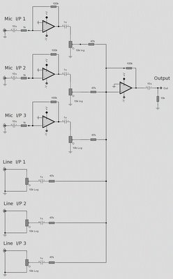
The microphone inputs are amplified approximately 100 times or 40 dB, with the total gain of the mixer, including the summing amplifier, reaching 46 dB. The microphone input is designed for microphones that produce an output of around 2...

If you have ever wondered why the Stop/Turn signal lamps on your trailer appear dim, you are not alone. The reason for this is that the typical Stop & Turn Signal Converter... The dimming of trailer Stop/Turn signal lamps is...
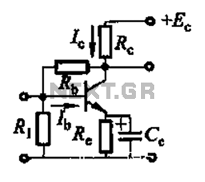
Basic reference transistor bias circuit - Mixed Negative feedback The basic reference transistor bias circuit utilizing mixed negative feedback is a fundamental electronic configuration designed to stabilize the operating point of a transistor. This circuit typically employs a combination of...
This FET audio mixer demonstrates the versatility of FETs. Originally designed for high-frequency applications, FETs can also effectively handle audio frequencies, showcasing exceptional performance in this domain. The circuit can accommodate an unlimited number of inputs, provided that the...
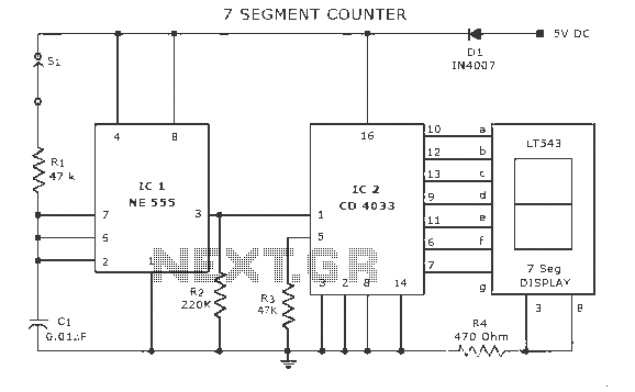
A display counter circuit is illustrated through a diagram featuring a seven-segment display controlled by the counter IC CD4033. This counter circuit is designed to visually represent incremental counts, enhancing its appeal for integration into various applications. An astable...
Warning: include(partials/cookie-banner.php): Failed to open stream: Permission denied in /var/www/html/nextgr/view-circuit.php on line 713
Warning: include(): Failed opening 'partials/cookie-banner.php' for inclusion (include_path='.:/usr/share/php') in /var/www/html/nextgr/view-circuit.php on line 713