
555 simple electronic keyboard circuit (2)
The multivibrator circuit based on the 555 timer is a versatile configuration used for generating pulse-width modulation signals, oscillations, and timing applications. The core of the circuit relies on the 555 timer IC, which can operate in astable, monostable, or bistable modes. In this configuration, it operates in astable mode, where it continuously oscillates between high and low states, generating a square wave output.
The frequency of oscillation, as indicated, is calculated using the formula f = 1.44 / ((Ra + 2R16) * C3). Here, Ra is the resistance value that can be adjusted by selecting different resistors from R1 to R15, allowing for flexibility in the circuit's frequency response. R16 serves as an additional resistor that influences the timing characteristics, while C3 is the timing capacitor that works in conjunction with the resistors to set the frequency of oscillation.
The keys K1 to K15 can serve as input controls that modify the resistance value of Ra. When a key is pressed, it can either connect or disconnect certain resistors in parallel or series, thus changing the effective resistance and, consequently, the frequency of the output signal. This feature allows for user interaction, enabling dynamic adjustments to the oscillation frequency based on operational requirements.
During the debugging phase, it is crucial to monitor the output waveform using an oscilloscope to ensure that the desired frequency and duty cycle are achieved. Adjustments can be made to the resistor and capacitor values to fine-tune the performance of the multivibrator. Additionally, it is advisable to take note of any anomalies in the output that could indicate issues with component values or connections within the circuit. Proper documentation of these observations will facilitate troubleshooting and optimization of the multivibrator circuit.As the figure 14-41 shows, the multivibrator is composed of the 555 and some capacitance resistance components, the oscillation frequency depends on the values of Ra, R16 and C3. f=1.44/(Ra+2R16)C3, the Ra of the formula corresponds to the different values of R1-R15, this depends on the situation of the keys K1-K15.
When you are debugging the notes, you can.. 🔗 External reference
Related Circuits

This circuit is a constant current protection type that limits the output current to a specific value in cases of over-current and short-circuit conditions. When the output current exceeds this limit, the output voltage decreases. The CW200 power management...

This is a design circuit diagram of a moderate power FM transmitter circuit. The circuit operates using two transistors. It consists of a complete circuit diagram. The operation of this circuit is explained as follows: the voice signals picked...
Nowadays electronic voting machines are being used effectively. The confidence of the voter in its flawless working is gradually building up and these machines are thus becoming quite popular throughout the country. Features of the electronic voting machine include...

A diode is utilized in a temperature sensor application circuit. Silicon diodes VD1 and VD2 serve as the temperature sensors, exhibiting a temperature coefficient of silicon diodes. The circuit includes a constant current source, VT1, which provides a steady...
This circuit is a simple and cost-effective design that utilizes an operational amplifier IC 741 (IC1) alongside a push-pull amplifier made with transistors for signal amplification. The project name indicates its intended application, which includes level control in hydroponic...
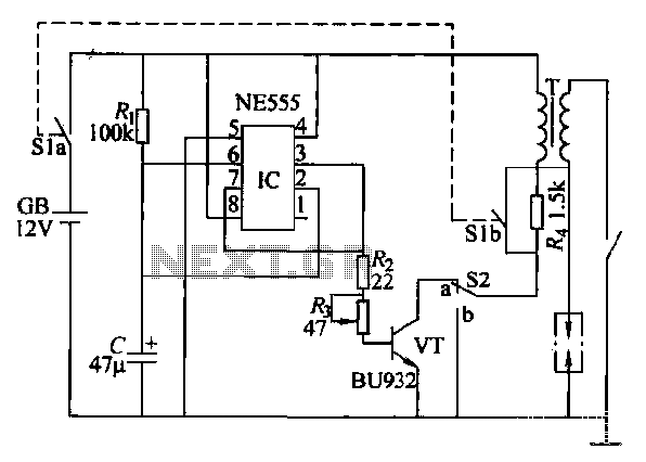
This paragraph describes an easy car alarm circuit that utilizes fewer components and is simple to produce. The circuit consists of an automobile anti-theft alarm system based on the NE555 timer, a power switch (VT), and a switch (S2),...