
medium power fm transmitter circuit

The described FM transmitter circuit is designed to operate with moderate power levels, making it suitable for short-range audio transmission. The circuit employs two transistors, Q1 and Q2, where Q1 serves primarily as an audio amplifier. When a voice signal is captured by the microphone, it is converted into an electrical signal that Q1 amplifies, enhancing the signal strength for further processing.
The second transistor, Q2, is configured as an oscillator. It generates a carrier wave in the FM band, which is modulated by the amplified audio signal from Q1. The modulation process occurs as the output from Q1 is fed into the base of Q2, enabling Q2 to vary the frequency of the carrier wave in accordance with the audio signal's amplitude.
The frequency of the oscillator is determined by the tank circuit formed by inductor L1 and capacitor C6. The value of C6 can be adjusted to change the oscillation frequency, allowing for tuning to the desired FM frequency. This feature is essential for complying with regulatory standards and avoiding interference with other radio services.
Capacitor C7 plays a critical role in coupling the modulated FM signal to the antenna. This coupling ensures that the transmitted signal is efficiently radiated into the surrounding environment. The inductor L1, constructed from enameled copper wire, is designed to provide the necessary inductance for the tank circuit. The physical characteristics of L1, such as the number of turns and the dimensions of the former, are important for achieving the desired frequency response.
To maximize the transmitter's performance, a matching antenna, A1, is recommended. A 1-meter long wire antenna is appropriate for this application and can significantly enhance the transmission range. With proper tuning and adjustments, the circuit can achieve an operational range of up to 100 meters, making it suitable for various applications such as hobbyist projects, educational demonstrations, or personal use.
Powering the circuit with a 9V PP3 battery ensures portability and ease of use. This power supply is sufficient to drive the transistors and support the overall operation of the circuit, making it an effective solution for moderate power FM transmission.This is a design circuit diagram of a moderate power FM transmitter circuit. This circuit is built operation by two transistors. This is a figure of complete circuit. Operation of this circuit is explain as the voice signals picked by the microphone will be amplified by the transistor Q1. The second transistor is wired as an oscillator operating in the FM band. The output of T1 is given to the base of T2. T2 performs the modulation also. The tank circuit comprising of components L1 and C6 determines the frequency of the signal, and can be varied by adjusting C6. The capacitor C7 couples the FM signal to the antenna. The inductor L1 can be made by making 6 turns of 0. 8mm enameled copper wire on a 5. 5mm diameter/4. 5mm length plastic former. With a matching antenna and proper tuning this transmitter can have range up to 100 meter. The Antenna A1 can be a 1M long wire. The circuit can be powered from a9V PP3 battery. 🔗 External reference
Related Circuits
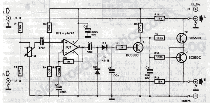
This stereo noise blanker or suppressor attenuates noise by 45 dB when the music signal is low or absent; it functions primarily as a noise limiter. The noise blanker sensitivity... This circuit serves as a stereo noise blanker or suppressor,...
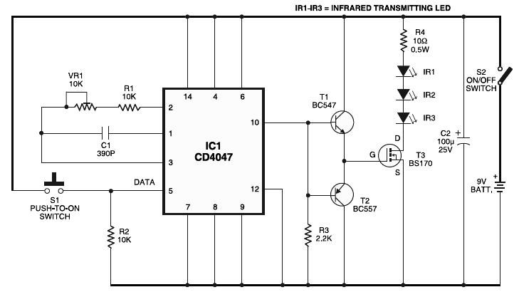
Long-distance infrared transmitter circuit diagram. This simple circuit offers a considerable range by utilizing three infrared transmitting LEDs (IR1 through IR3) in series to enhance the radiated power. To further improve directivity and power density, the IR LEDs can...
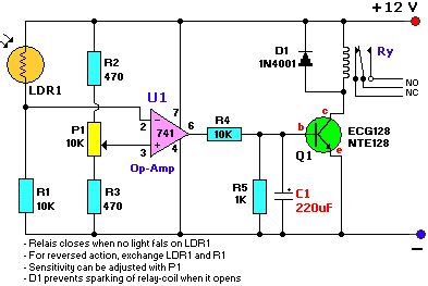
The schematic diagram has been modified to include a 220µF smoothing capacitor connected between the base of transistor Q1 and ground. This addition effectively mitigated the issue of relay chatter, which involved rapid on/off switching at light levels. The...
To order boards, click to access the ESP Purchase form. Verify the price and postage, then open the order form, fill it in, and print it from your browser. Boards are sold only as a stereo pair and are...
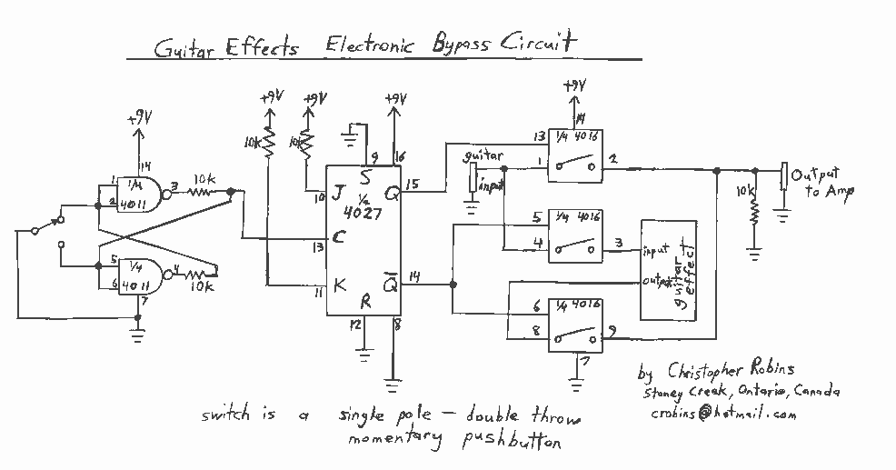
Observing my Boss pedals and how they were switched on and off I figured there must be more to it. It took me only about 4 hours to design and test this circuit. It works very well and I’m...
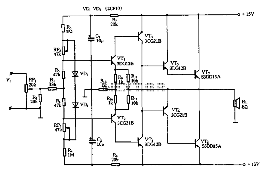
The circuit utilizes diode VDi, f Pooh to stabilize the base bias of transistors VTi and VT2, ensuring a more stable quiescent point when the supply voltage is within a specific range. In the event of temperature fluctuations, the...
Warning: include(partials/cookie-banner.php): Failed to open stream: Permission denied in /var/www/html/nextgr/view-circuit.php on line 713
Warning: include(): Failed opening 'partials/cookie-banner.php' for inclusion (include_path='.:/usr/share/php') in /var/www/html/nextgr/view-circuit.php on line 713