
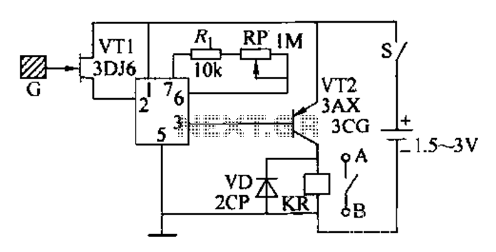
Induction automatic switch circuit
The constant current protection circuit is essential in safeguarding electronic systems from damage due to excessive current conditions. The design effectively utilizes a combination of components to ensure that the output current remains within safe limits during fault conditions. The Zener diode plays a critical role in voltage regulation by providing a stable reference voltage, which is crucial for the operation of the transistor VT1. When the output current exceeds the threshold, the sensing resistor R detects this increase and triggers the conduction of VT1, thereby limiting the output current and protecting downstream components.
The configuration of the resistors RP2 and RP3 allows for precise adjustments to the circuit's performance. RP2 is particularly important for setting the maximum allowable output current, while RP3 adjusts the rate at which the output voltage decreases during overcurrent conditions. This flexibility ensures that the circuit can be tailored to meet the specific requirements of various applications.
Thermal management is another critical aspect of the circuit design. The CW200 regulator must be equipped with an adequately sized heat sink to dissipate the heat generated during operation, especially under high load conditions. The heat sink must be selected based on the expected power dissipation, which involves calculating the difference between the input voltage and the output voltage multiplied by the output current. This calculation ensures that the temperature of the regulator remains within safe operating limits, thereby enhancing the reliability and longevity of the circuit.
Finally, the inclusion of input and output capacitors is vital to stabilize the circuit and prevent oscillations that could lead to erratic behavior. Careful selection of these capacitors, considering their equivalent series resistance (ESR) and capacitance values, contributes significantly to the overall stability and performance of the constant current protection circuit.Constant current protection circuit type, since the over-current and short-circuit, the output current is limited only to a certain value, the output voltage drops, the overcur rent room a little longer, power management and power CW200 is still possible due to excessive damage. Shown for the reduced flow high current regulator 12-44. It lies in the use of Zener diode vs impact on VT1: When the amount exceeds the value of the output current flows through the sensing resistor R., The protective crystal tube VT1 conduction, the circuit into a constant-current protection status.
When the output voltage drops to the implicit value of the pressure regulator diode vs UD time (10V) or less, vs by VD2, RP3, RP2 to the base of VT1 injection current causes the output voltage Uo into a further decline, vs will be maintained in CW200 protection status main factor, R. Pressure drop becomes a secondary factor, which played a protection device and power tube effect. Circuit RP2 to micro adjust the current limit, RP3 used to adjust the degree of reduction processes. A brief review of the integrated regulator CW200 three basic usage. When using this regulator, should pay attention to add enough wattage large heat sink, a heat sink in accordance with Pw Jo (U, - soul) estimate, where L is the output current, U; the input voltage, U is value of the output voltage t goblets -UO to 5-8v appropriate.
When using the regulator input and output capacitor must eliminate vibration with no sense of capacitors.
Related Circuits
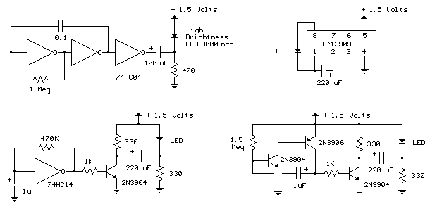
The LED flasher circuits below operate on a single 1.5 volt battery. The circuit on the upper right uses the popular LM3909 LED flasher IC and requires only a timing capacitor and LED. The top left circuit, designed by...
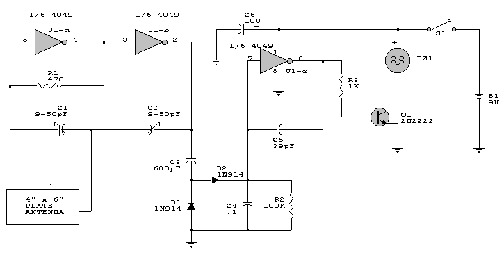
This is a simple proximity switch utilizing the IC 4049. The IC 4049 is a bipolar monolithic integrated circuit designed for metal detection systems and proximity sensing applications. It includes an oscillator formed by an external parallel resonant tank...
This compact water sensor alarm circuit emits a loud warning sound when a humidity sensor detects the presence of water. The circuit utilizes the low-power comparator LM1801 from National Semiconductor. A fixed reference voltage for the integrated circuit is...
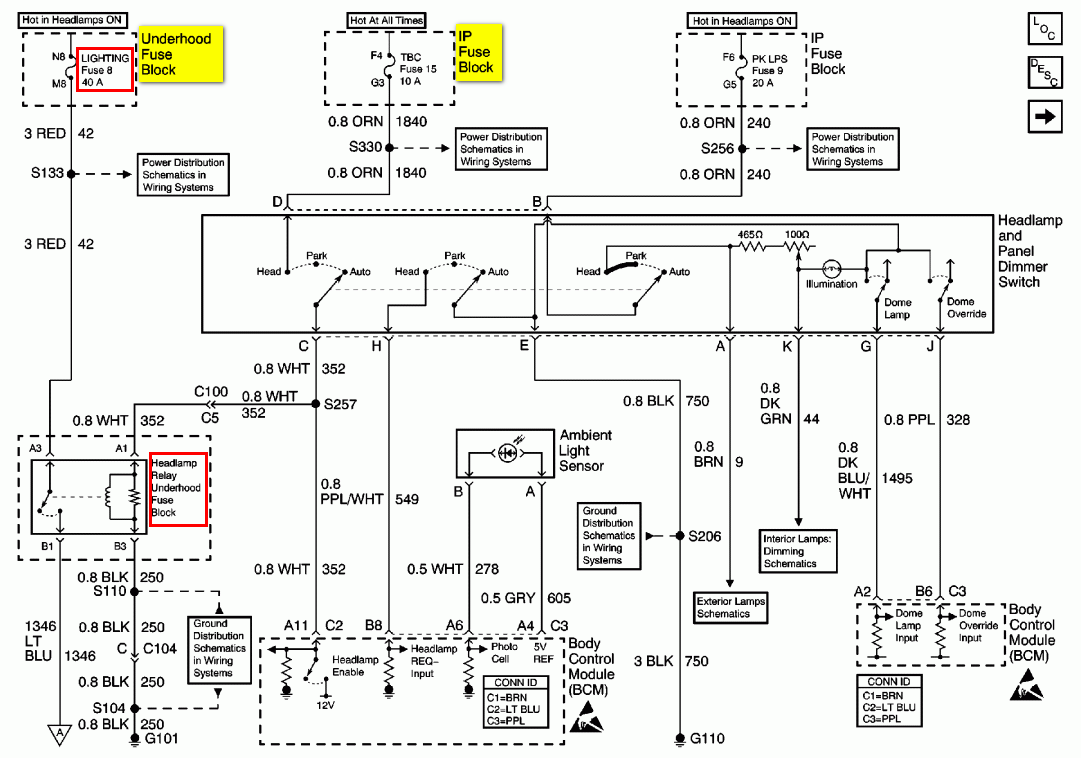
To troubleshoot the headlight system, switch the headlight switch ON and OFF and check if the headlight relay can be felt and heard clicking. This is indicated in the first schematic on the left side of the diagram. The...
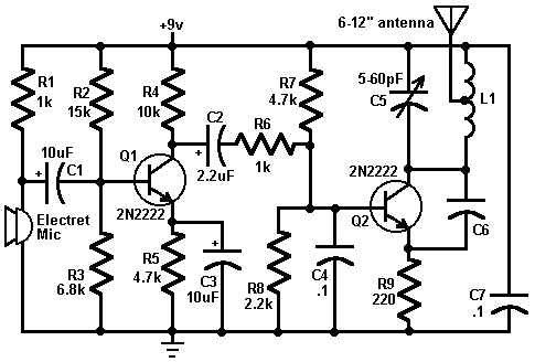
This circuit is a simple two-transistor (2N2222) mini FM transmitter. No authorization is required for this transmitter according to FCC regulations regarding wireless microphones. When powered by a 9-volt battery and equipped with an antenna no longer than 12...

This device functions as a convenient tool for testing infrared (IR) remote control transmitters used with televisions, VCRs, and similar devices. The IR signals emitted from a remote control are detected by the IR sensor module within the tester,...
Warning: include(partials/cookie-banner.php): Failed to open stream: Permission denied in /var/www/html/nextgr/view-circuit.php on line 713
Warning: include(): Failed opening 'partials/cookie-banner.php' for inclusion (include_path='.:/usr/share/php') in /var/www/html/nextgr/view-circuit.php on line 713